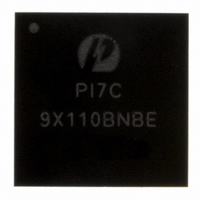
PI7C9X110BNBE Pericom Semiconductor, PI7C9X110BNBE Datasheet - Page 30

PI7C9X110BNBE
Manufacturer Part Number
PI7C9X110BNBE
Description
IC PCIE TO PCI REV BRG 160LFBGA
Manufacturer
Pericom Semiconductor
Specifications of PI7C9X110BNBE
Applications
PCI-to-PCI Bridge
Interface
I²C
Voltage - Supply
1.8 V
Package / Case
160-LBGA
Mounting Type
Surface Mount
Operating Temperature (min)
-40C
Operating Temperature Classification
Industrial
Operating Temperature (max)
85C
Rad Hardened
No
Maximum Operating Temperature
+ 85 C
Minimum Operating Temperature
- 40 C
Mounting Style
SMD/SMT
Lead Free Status / RoHS Status
Lead free / RoHS Compliant
Lead Free Status / RoHS Status
Lead free / RoHS Compliant, Compliant
Available stocks
Company
Part Number
Manufacturer
Quantity
Price
Company:
Part Number:
PI7C9X110BNBE
Manufacturer:
PLX
Quantity:
1 238
Company:
Part Number:
PI7C9X110BNBE
Manufacturer:
PERICOM31
Quantity:
193
Part Number:
PI7C9X110BNBE
Manufacturer:
PERICOM
Quantity:
20 000
7.2
Note 1: When masquerade is enabled, it is pre-loadable.
Note 2: When both masquerade and non-transparent mode are enabled, it is pre-loadable.
Note 3: When non-transparent mode is enabled, it is pre-loadable.
Note 4: The VPD data is read/write through I2C during VPD operation.
Note 5: Read access only.
PI7C9X110 also supports PCI Express Extended Capabilities with from 257-byte to 4096-byte space. The offset
range is from 100h to FFFh. The offset 100h is defined for Advance Error Reporting (ID=0001h). The offset 150h
is defined for Virtual Channel (ID=0002h).
Table 7-2 PCI Express Extended Capability Register Map (100h – FFFh)
Pericom Semiconductor – Confidential
PCI EXPRESS EXTENDED CAPABILITY REGISTER MAP
Primary Bus
Configuration Access
for both Transparent
and Non-Transparent
mode, or Secondary
Bus Configuration
Access for Transparent
Mode
E3h – E0h
E7h – E4h
EBh – E8h
EFh – ECh
F3h – F0h
F7h – F4h
FBh – F8h
FFh – FCh
Primary Bus
Configuration Access
for both Transparent
and Non-Transparent
mode, or Secondary
Bus Configuration
Access for Transparent
Mode
103h – 100h
107h – 104h
10Bh – 108h
10Fh – 10Ch
113h – 110h
117h – 114h
11Bh – 118h
12Bh – 11Ch
12Fh – 12Ch
Secondary Bus
Configuration Access
for Non-Transparent
Mode Only
E3h – E0h
E7h – E4h
EBh – E8h
EFh – ECh
F3h – F0h
F7h – F4h
FBh – F8h
FFh – FCh
Secondary Bus
Configuration Access
for Non-Transparent
Mode Only
103h – 100h
107h – 104h
10Bh – 108h
10Fh – 10Ch
113h – 110h
117h – 114h
11Bh – 118h
12Bh – 11Ch
12Fh – 12Ch
Page 30 of 144
Transparent Mode
(type1)
Reserved
Reserved
Reserved
Reserved
MSI Capability
Register
Message Address
Message Upper
Address
Message Date
Transparent Mode
(type1)
Advanced Error
Reporting (AER)
Capability
Uncorrectable Error
Status
Uncorrectable Error
Mask
Uncorrectable Severity
Correctable Error
Status
Correctable Error
Mask
AER Control
Header Log Register
Secondary
Uncorrectable Error
Status
Non-Transparent
Mode (Type0)
Upstream Memory 0
Translated Base
Upstream Memory 0
setup
Upstream I/O or
Memory 1 Translated
Base
Upstream I/O or
Memory 1 Setup
MSI Capability
Register
Message Address
Message Upper
Address
Message Date
Non-Transparent
Mode (Type0)
Advanced Error
Reporting (AER)
Capability
Uncorrectable Error
Status
Uncorrectable Error
Mask
Uncorrectable Severity
Correctable Error
Status
Correctable Error
Mask
AER Control
Header Log Register
Secondary
Uncorrectable Error
Status
April 2010, Revision 3.0
PCIe-to-PCI Reversible Bridge
EEPROM
(I2C)
Access
No
Yes
No
Yes
No
No
No
No
EEPROM
(I2C)
Access
No
No
No
No
No
No
No
No
No
3
3
PI7C9X110
SM Bus
Access
Yes
Yes
Yes
Yes
Yes
Yes
Yes
Yes
SM Bus
Access
Yes
Yes
Yes
Yes
Yes
Yes
Yes
Yes
Yes
3
3
5


