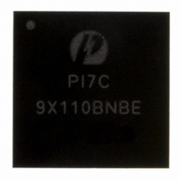
PI7C9X110BNBE Pericom Semiconductor, PI7C9X110BNBE Datasheet - Page 132

PI7C9X110BNBE
Manufacturer Part Number
PI7C9X110BNBE
Description
IC PCIE TO PCI REV BRG 160LFBGA
Manufacturer
Pericom Semiconductor
Specifications of PI7C9X110BNBE
Applications
PCI-to-PCI Bridge
Interface
I²C
Voltage - Supply
1.8 V
Package / Case
160-LBGA
Mounting Type
Surface Mount
Operating Temperature (min)
-40C
Operating Temperature Classification
Industrial
Operating Temperature (max)
85C
Rad Hardened
No
Maximum Operating Temperature
+ 85 C
Minimum Operating Temperature
- 40 C
Mounting Style
SMD/SMT
Lead Free Status / RoHS Status
Lead free / RoHS Compliant
Lead Free Status / RoHS Status
Lead free / RoHS Compliant, Compliant
Available stocks
Company
Part Number
Manufacturer
Quantity
Price
Company:
Part Number:
PI7C9X110BNBE
Manufacturer:
PLX
Quantity:
1 238
Company:
Part Number:
PI7C9X110BNBE
Manufacturer:
PERICOM31
Quantity:
193
Part Number:
PI7C9X110BNBE
Manufacturer:
PERICOM
Quantity:
20 000
9
10
11
PCI Express interface:
PI7C9X110 requires 100MHz differential clock inputs through REFCLKP and REFCLKN Pins.
PCI interface:
PI7C9X110 requires PCI clock (up to 66MHz and at least 10MHz) to be connected to the CLKIN. PI7C9X110 uses
the CLKIN and generates nine clock outputs, CLKOUT [8:0]. Also, PI7C9X110 requires one of the CLKOUT
[8:0] (preferably CLKOUT [8]) to be connected to FBCLKIN for the PCI interface logic of PI7C9X110. The actual
number of masters supported will vary depending on the loading of the PCI bus. Typically, PI7C9X110 can support
up to four 66MHz PCI slots or eight 33MHz PCI slots.
The PI7C9X110 PCI Clock Outputs, CLKOUT [8:0], can be enabled or disabled through the configuration register.
PI7C9X110 supports interrupt message packets on PCIe side. PI7C9X110 supports PCI interrupt (INTA, B, C, D)
pins or MSI (Message Signaled Interrupts) on PCI side. PCI interrupts and MSI are mutually exclusive. In order
words, if MSI is enabled, PCI interrupts will be disabled. PI7C9X110 support 64-bit addressing MSI.
In reverse bridge mode, PI7C9X110 maps the interrupt message packets to PCI interrupt pins or MSI if MSI is
enable (see configuration register bit [16] of Offset F0h).
In forward bridge mode, PI7C9X110 maps the PCI interrupts pins or MSI if enable on PCI side to interrupt message
packets on PCIe side.
There are eight interrupt message packets. They are Assert_INTA, Assert_INTB, Assert_INTC, Assert_INTD,
Deassert_INTA, Deassert_INTB, Deassert_INTC, and Deassert_INTD. These eight interrupt messages are mapped
to the four PCI interrupts (INTA, INTB, INTC, and INTD). See Table 10-1 for interrupt mapping information in
reverse bridge mode. PI7C9X110 tracks the PCI interrupt (INTA, INTB, INTC, and INTD) pins and maps them to
the eight interrupt messages. See Table 10-2 for interrupt mapping information in forward bridge mode.
Table 10-1 PCIe interrupt message to PCI interrupt mapping in reverse bridge mode
Pericom Semiconductor – Confidential
CLOCK SCHEME
INTERRUPTS
EEPROM (I2C) INTERFACE AND SYSTEM MANAGEMENT BUS
PCIe Interrupt messages (from sources of interrupt)
INTA message
INTB message
INTC message
INTD message
PCI Interrupts (from sources of interrupts)
INTA
INTB
INTC
INTD
Table 10-2 PCI interrupt to PCIe interrupt message mapping in forward bridge mode
Page 132 of 144
PCI Interrupts (to host controller)
INTA
INTB
INTC
INTD
PCIe Interrupt message packets (to host controller)
INTA message
INTB message
INTC message
INTD message
April 2010, Revision 3.0
PCIe-to-PCI Reversible Bridge
PI7C9X110


