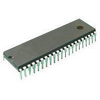
ST72C334N2B6 STMicroelectronics, ST72C334N2B6 Datasheet - Page 57

ST72C334N2B6
Manufacturer Part Number
ST72C334N2B6
Description
Microcontrollers (MCU) Flash 8K SPI/SCI
Manufacturer
STMicroelectronics
Datasheet
1.ST72C334N2T6.pdf
(126 pages)
Specifications of ST72C334N2B6
Data Bus Width
8 bit
Program Memory Type
Flash
Program Memory Size
8 KB
Data Ram Size
384 B
Interface Type
SCI, SPI
Maximum Clock Frequency
8 MHz
Number Of Programmable I/os
44
Number Of Timers
16 bit
Operating Supply Voltage
3.2 V to 5.5 V
Maximum Operating Temperature
+ 85 C
Mounting Style
Through Hole
Package / Case
SDIP-56
Minimum Operating Temperature
- 40 C
On-chip Adc
8 bit
Lead Free Status / Rohs Status
No
Available stocks
Company
Part Number
Manufacturer
Quantity
Price
Company:
Part Number:
ST72C334N2B6
Manufacturer:
ST
Quantity:
365
16-BIT TIMER (Cont’d)
6.4.3.3 Input Capture
In this section, the index, i , may be 1 or 2.
The two input capture 16-bit registers (IC1R and
IC2R) are used to latch the value of the free run-
ning counter after a transition detected by the
ICAP i pin (see figure 5).
IC i register is a read-only register.
The active transition is software programmable
through the IEDG i bit of the Control Register (CR i ).
Timing resolution is one count of the free running
counter: (
Procedure:
To use the input capture function select the follow-
ing in the CR2 register:
– Select the timer clock (CC1-CC0) (see Table 14
– Select the edge of the active transition on the
And select the following in the CR1 register:
– Set the ICIE bit to generate an interrupt after an
– Select the edge of the active transition on the
Clock Control Bits).
ICAP2 pin with the IEDG2 bit (the ICAP2 pin
must be configured as floating input).
input capture coming from both the ICAP1 pin or
the ICAP2 pin
ICAP1 pin with the IEDG1 bit (the ICAP1pin must
be configured as floating input).
ICiR
f
CPU
/(CC1.CC0)
MS Byte
IC i HR
).
LS Byte
IC i LR
When an input capture occurs:
– ICF i bit is set.
– The IC i R register contains the value of the free
– A timer interrupt is generated if the ICIE bit is set
Clearing the Input Capture interrupt request is
done in two steps:
1. Reading the SR register while the ICF i bit is set.
2. An access (read or write) to the IC i LR register.
Notes:
2. After reading the IC i HR register, transfer of
3. The IC i R register always contains the free run-
4. The 2 input capture functions can be used
5. In One pulse Mode and PWM mode only the
6. The alternate inputs (ICAP1 & ICAP2) are
7. Moreover if one of the ICAP i pin is configured
8. The TOF bit can be used with interrupt in order
running counter on the active transition on the
ICAP i pin (see Figure 40).
and the I bit is cleared in the CC register. Other-
wise, the interrupt remains pending until both
conditions become true.
input capture data is inhibited until the IC i LR
register is also read.
ning counter value which corresponds to the
most recent input capture.
together even if the timer also uses the output
compare mode.
input capture 2 can be used.
always directly connected to the timer. So any
transitions on these pins activate the input cap-
ture process.
as an input and the second one as an output,
an interrupt can be generated if the user toggle
the output pin and if the ICIE bit is set.
to measure event that go beyond the timer
range (FFFFh).
ST72334J/N, ST72314J/N, ST72124J
57/125


