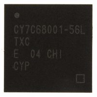
CY7C68001-56LTXC Cypress Semiconductor Corp, CY7C68001-56LTXC Datasheet - Page 2

CY7C68001-56LTXC
Manufacturer Part Number
CY7C68001-56LTXC
Description
IC USB EZ-USB SX2 HS 56VQFN
Manufacturer
Cypress Semiconductor Corp
Series
CY7Cr
Type
USBr
Specifications of CY7C68001-56LTXC
Protocol
USB 2.0
Voltage - Supply
3 V ~ 3.6 V
Mounting Type
Surface Mount
Package / Case
56-VQFN Exposed Pad, 56-HVQFN, 56-SQFN, 56-DHVQFN
Lead Free Status / RoHS Status
Lead free / RoHS Compliant
Number Of Drivers/receivers
-
Lead Free Status / Rohs Status
Lead free / RoHS Compliant
Other names
428-2932
Available stocks
Company
Part Number
Manufacturer
Quantity
Price
Part Number:
CY7C68001-56LTXC
Manufacturer:
CYPRESS/赛普拉斯
Quantity:
20 000
1.0 EZ-USB SX2™ FEATURES ............................................................................................................. 7
2.0 APPLICATIONS ............................................................................................................................... 8
3.0 FUNCTIONAL OVERVIEW .............................................................................................................. 9
4.0 ENUMERATION ............................................................................................................................. 15
5.0 ENDPOINT 0 .................................................................................................................................. 16
6.0 PIN ASSIGNMENTS ...................................................................................................................... 17
7.0 REGISTER SUMMARY .................................................................................................................. 21
Document #: 38-08013 Rev. *B
1.1 Introduction ............................................................................................................................... 7
1.2 Features ..................................................................................................................................... 7
1.3 Block Diagram ........................................................................................................................... 7
2.1 System Diagram ........................................................................................................................ 8
3.1 USB Signaling Speed ............................................................................................................... 9
3.2 Buses ......................................................................................................................................... 9
3.3 Boot Methods ............................................................................................................................ 9
3.4 Interrupt System ..................................................................................................................... 10
3.5 Resets and Wakeup ................................................................................................................ 11
3.6 Endpoint RAM ......................................................................................................................... 11
3.7 External Interface .................................................................................................................... 12
4.1 Standard Enumeration ........................................................................................................... 15
4.2 Default Enumeration ............................................................................................................... 16
6.1 56-pin SSOP ............................................................................................................................ 17
6.2 56-pin QFN ............................................................................................................................... 18
6.3 CY7C68001 Pin Descriptions ................................................................................................. 19
7.1 IFCONFIG Register 0x01 ........................................................................................................ 22
3.3.1 EEPROM Organization .................................................................................................................... 9
3.3.2 Default Enumeration ..................................................................................................................... 10
3.4.1 Architecture ...................................................................................................................................10
3.4.2 ITENABLE Register Bit Definition ............................................................................................... 10
3.5.1 Reset .............................................................................................................................................. 11
3.5.2 USB Reset ...................................................................................................................................... 11
3.5.3 Wakeup ..........................................................................................................................................11
3.6.1 Size ................................................................................................................................................. 11
3.6.2 Organization .................................................................................................................................. 11
3.6.3 Endpoint Configurations (High-speed Mode) ............................................................................. 12
3.6.4 Default Endpoint Memory Configuration .................................................................................... 12
3.7.1 Architecture ...................................................................................................................................12
3.7.2 Control Signals ..............................................................................................................................13
3.7.3 IFCLK .............................................................................................................................................. 13
3.7.4 FIFO Access .................................................................................................................................. 13
3.7.5 FIFO Flag Pins Configuration ...................................................................................................... 14
3.7.6 Default FIFO Programmable Flag Set-up .................................................................................... 14
3.7.7 FIFO Programmable Flag (PF) Set-up ......................................................................................... 14
3.7.8 Command Protocol ....................................................................................................................... 14
7.1.1 Bit 7: IFCLKSRC ............................................................................................................................ 22
7.1.2 Bit 6: 3048MHZ ..............................................................................................................................22
7.1.3 Bit 5: IFCLKOE ..............................................................................................................................22
TABLE OF CONTENTS
CY7C68001
Page 2 of 50


