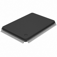
DS21Q42T+ Maxim Integrated Products, DS21Q42T+ Datasheet - Page 76

DS21Q42T+
Manufacturer Part Number
DS21Q42T+
Description
IC FRAMER ENHANCED T1 4X 128TQFP
Manufacturer
Maxim Integrated Products
Datasheet
1.DS21Q42T.pdf
(116 pages)
Specifications of DS21Q42T+
Controller Type
T1 Framer
Interface
Parallel/Serial
Voltage - Supply
2.97 V ~ 3.63 V
Current - Supply
75mA
Operating Temperature
0°C ~ 70°C
Mounting Type
Surface Mount
Package / Case
128-TQFP, 128-VQFP
Lead Free Status / RoHS Status
Lead free / RoHS Compliant
17.
Each of the 24 T1 channels in the transmit direction of the framer can be either forced to be transparent or
in other words, can be forced to stop Bit 7 Stuffing and/or Robbed Signaling from overwriting the data in
the channels. Transparency can be invoked on a channel by channel basis by properly setting the TTR1,
TTR2, and TTR3 registers.
TTR1/TTR2/TTR3: TRANSMIT TRANSPARENCY REGISTER
(Address=39 to 3B Hex)
Each of the bit position in the Transmit Transparency Registers (TTR1/TTR2/TTR3) represent a DS0
channel in the outgoing frame. When these bits are set to a one, the corresponding channel is transparent
(or clear). If a DS0 is programmed to be clear, no robbed bit signaling will be inserted nor will the
channel have Bit 7 stuffing performed. However, in the D4 framing mode, bit 2 will be overwritten by a
zero when a Yellow Alarm is transmitted. Also the user has the option to prevent the TTR registers from
determining which channels are to have Bit 7 stuffing performed. If the TCR2.0 and TCR1.3 bits are set
to one, then all 24 T1 channels will have Bit 7 stuffing performed on them regardless of how the TTR
registers are programmed. In this manner, the TTR registers are only affecting which channels are to
have robbed bit signaling inserted into them. Please see Figure 20-15 for more details.
18.
In many architectures, the outputs of individual framers are combined into higher speed serial buses to
simplify transport across the system. The DS21Q42 can be configured to allow each framer’s data and
signaling busses to be multiplexed into higher speed data and signaling busses eliminating external
hardware saving board space and cost.
The interleaved PCM bus option supports two bus speeds and interleave modes. The 4.096 MHz bus
speed allows two framers to share a common bus. The 8.192 MHz bus speed allows all four of the
DS21Q42’s framers to share a common bus. Framers can interleave their data either on byte or frame
boundaries. Framers that share a common bus must be configured through software and require several
device pins to be connected together externally (see figures 18-1 & 18-2). Each framer’s elastic stores
must be enabled and configured for 2.048 MHz operation. The signal RSYNC must be configured as an
input on each framer.
(MSB)
CH16
CH24
CH8
SYMBOLS
CH1-24
TRANSMIT TRANSPARENCY
INTERLEAVED PCM BUS OPERATION
CH15
CH23
CH7
CH14
CH22
POSITIONS
CH6
TTR1.0-3.7
CH13
CH21
CH5
NAME AND DESCRIPTION
Transmit Transparency Registers.
0 = this DS0 channel is not transparent
1 = this DS0 channel is transparent
CH12
CH20
CH4
76 of 116
CH19
CH11
CH3
CH10
CH18
CH2
(LSB)
CH17
CH1
CH9
TTR2 (3A)
TTR3 (3B)
TTR1 (39)


