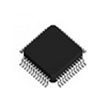
IDTSTAC9758XXTAEB1XR IDT, Integrated Device Technology Inc, IDTSTAC9758XXTAEB1XR Datasheet - Page 72

IDTSTAC9758XXTAEB1XR
Manufacturer Part Number
IDTSTAC9758XXTAEB1XR
Description
IC CODEC AC'97 6CH 2.3 48-TQFP
Manufacturer
IDT, Integrated Device Technology Inc
Type
Audio Codec '97r
Datasheet
1.IDTSTAC9758XXTAEB1XR.pdf
(119 pages)
Specifications of IDTSTAC9758XXTAEB1XR
Data Interface
Serial
Resolution (bits)
20 b
Number Of Adcs / Dacs
2 / 3
Sigma Delta
Yes
Voltage - Supply, Analog
3.14 V ~ 3.47 V; 4.75 V ~ 5.25 V
Voltage - Supply, Digital
3.14 V ~ 3.47 V
Operating Temperature
0°C ~ 70°C
Mounting Type
Surface Mount
Package / Case
48-TQFP, 48-VQFP
Single Supply Voltage (typ)
3.3/5V
Single Supply Voltage (min)
3.135V
Single Supply Voltage (max)
3.465/5.25V
Package Type
TQFP
Lead Free Status / RoHS Status
Lead free / RoHS Compliant
Other names
STAC9758XXTAEB1XR
Available stocks
Company
Part Number
Manufacturer
Quantity
Price
Company:
Part Number:
IDTSTAC9758XXTAEB1XR
Manufacturer:
IDT, Integrated Device Technology Inc
Quantity:
10 000
IDT™
HIGH-PERFORMANCE 6-CHANNEL AC’97 2.3 CODEC WITH UNIVERSAL JACKS™
STAC9758/9759
HIGH-PERFORMANCE 6-CHANNEL AC’97 2.3 CODEC WITH UNIVERSAL JACKS™
8.2.20.
15:14
13:12
11:10
Bit
5:4
9
8
7
6
3
2
1
0
SDAC
D15
ID1
D7
Extended Audio ID (28h)
Default: 0BC7h
The Extended Audio ID register is a read only register except for bits D4 and D5. ID1 and ID0 echo
the configuration of the CODEC as defined by the programming of pin 46 externally. ID0 is always a
0 for the 9758. Code 00 returned defines the CODEC as the primary CODEC, while code 10 identi-
fies the CODEC as the secondary CODEC. The AMAP bit, D9, will return a 1 indicating that the
CODEC supports the optional AC’97 2.3 compliant AC-Link slot to audio DAC mappings. The default
condition assumes that 00 are loaded in the DSA0 and DSA1 bits of the Extended Audio ID (Index
28h). With 0 in the DSA1 and DSA0 bits, the CODEC slot assignments are as per the AC’97 specifi-
cation recommendations. If the DSA1 and DSA0 bits do not contain 0, the slot assignments are as
per the table in the section describing the Extended Audio ID (Index 28h). The VRA bit, D0, will
return a 1, indicating that the CODEC supports the optional variable sample rate conversion as
defined by the AC’97 specification.
Note: 1. External CID pin status (from analog) these bits are the logical inversion of the pin
polarity (pin 46). These bits are zero if XTAL_OUT is grounded with an alternate external clock
source in primary mode only. Secondary mode can either be through BIT CLK driven or 24MHz
clock driver, with XTAL_OUT floating.
Note: 2. If pin 48 is held high at powerup, register 28h (Extended Audio ID) bit [2] will be held to
zero, to indicate the SPDIF is not available. Tie pin 48 to ground with a 10 K
SPDIF is enabled.
00 or 10
Reset
Value
00
10
00
1
1
1
1
0
1
1
1
CDAC
D14
ID0
D6
R/W
RW
RO
RO RESERVED Bits not used; should read back 00
RO
RO
RO
RO
RO
RO RESERVED Reserved
RO
RO
RO
DSA [1,0]
REV[1:0]
ID [1,0]
AMAP
CDAC
SPDIF
Name
LDAC
SDAC
DRA
VRA
DSA1
D13
D5
RESERVED
00 = XTAL_OUT grounded (note 1)
CID1#, CID0# = XTAL_OUT crystal or floating
Indicates CODEC is AC’97 Rev 2.3 compliant
Multi-channel slot support (Always = 1)
Low Frequency Effect DAC Supported
Surround DACs Supported
Center channel DAC Supported
DAC slot assignment
See DSA table below.
The DSA bits for DAC-A are ignored when Double Rate Audio DRA is
used. Slots 3&4 are used instead. The DRSS bits indicate which
secondary slots to use. DAC-B and DAC-C are unaffected by the DRA bit.
0 = SPDIF pulled high on reset, SPDIF disabled
1 = default, SPDIF enabled (Note 2)
Double Rate Audio Supported
Variable sample rates supported (Always = 1)
DSA0
D12
72
D4
RESERVED
REV1
D11
D3
Function
STAC9758/9759
SPDIF
REV0
D10
D2
AMAP
DRA
D9
D1
resistor to ensure
PC AUDIO
LDAC
VRA
V 1.2 1206
D8
D0


