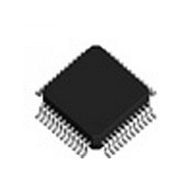
IDTSTAC9758XXTAEB1XR IDT, Integrated Device Technology Inc, IDTSTAC9758XXTAEB1XR Datasheet - Page 101

IDTSTAC9758XXTAEB1XR
Manufacturer Part Number
IDTSTAC9758XXTAEB1XR
Description
IC CODEC AC'97 6CH 2.3 48-TQFP
Manufacturer
IDT, Integrated Device Technology Inc
Type
Audio Codec '97r
Datasheet
1.IDTSTAC9758XXTAEB1XR.pdf
(119 pages)
Specifications of IDTSTAC9758XXTAEB1XR
Data Interface
Serial
Resolution (bits)
20 b
Number Of Adcs / Dacs
2 / 3
Sigma Delta
Yes
Voltage - Supply, Analog
3.14 V ~ 3.47 V; 4.75 V ~ 5.25 V
Voltage - Supply, Digital
3.14 V ~ 3.47 V
Operating Temperature
0°C ~ 70°C
Mounting Type
Surface Mount
Package / Case
48-TQFP, 48-VQFP
Single Supply Voltage (typ)
3.3/5V
Single Supply Voltage (min)
3.135V
Single Supply Voltage (max)
3.465/5.25V
Package Type
TQFP
Lead Free Status / RoHS Status
Lead free / RoHS Compliant
Other names
STAC9758XXTAEB1XR
Available stocks
Company
Part Number
Manufacturer
Quantity
Price
Company:
Part Number:
IDTSTAC9758XXTAEB1XR
Manufacturer:
IDT, Integrated Device Technology Inc
Quantity:
10 000
IDT™
HIGH-PERFORMANCE 6-CHANNEL AC’97 2.3 CODEC WITH UNIVERSAL JACKS™
STAC9758/9759
HIGH-PERFORMANCE 6-CHANNEL AC’97 2.3 CODEC WITH UNIVERSAL JACKS™
Bit(s) Reset Value R/W
7
6
5
4
3
2
1
0
0
0
0
0
0
0
0
0
RW
RW SPLITMUTE
RW
RW
RW
RW
RO DPLL_LOCK
RO
PR_DAC_A
INT_APOP
STMICEN
SIFOVRN
SP_RUN
SIPER
Name
0 = Anti Pop Enabled
1 = Anti Pop Disabled
The STAC9758/9759 includes an internal power supply anti-pop circuit
that prevents audible clicks and pops from being heard when the CODEC
is powered on and off. This function is accomplished by delaying the
charge/discharge of the VREF capacitor (Pin 27). C
cause a turn-on delay of roughly 3 seconds, which will allow the power
supplies to stabilize before the CODEC outputs are enabled. The delay
will be extended to 30 seconds if a value of C
The CODEC outputs are also kept stable for the same amount of time at
power-off to allow the system to be gracefully turned off. The INT_APOP
bit allows this delay circuit to be bypassed for rapid production testing. Any
external component anti-pop circuit is unaffected by the internal circuit.
Allows separate mute control bits for Master, Headphone, LineIN, CD,
AUX and PCM
volume control registers as well as Record Gain register.
0 = Default Value: Left and Right channel mutes are controlled by bit D15
of the respective registers disables writes to all R mute signals and force
them to read 0.
1 = Bit D15 of respective register affects only the Left channel Mute and bit
D7 affects only the Right Channel Mute enables read and writes to Rmute
bit in all Stereo Volume registers.
If SPLITMUTE is not set, the bahavior is the same as previous CODECs.
SPDIF_IN FIFO OVERRUN STATUS BIT
0 = no overrun occurred (defualt)
1 = overrun has occurred
SPDIF_IN PARITY ERROR
0 = no parity error occurred (defualt)
1 = parity error occurred
Digital PLL Lock
0 = DPLL not locked
1 = DPLL locked to SPDIF _IN and data valid
SPDIF Running
0 = no signal on pin 47
1 = signal on pin 47
Powerdown bit for first DAC
1 = powerdown
0 = normal operation
This is equivalent to PRI, PRJ, and PRK, but applies to the first DAC which
is not otherwise accomodated
Stereo Mic Enable
0 = Mono
1 = Stereo
If this bit is 1, then Reg 20h, D8, causes left/right swap when set to 1.
101
Description
STAC9758/9759
VREF
value of 10 F is used.
VREF
value of 1 F will
PC AUDIO
V 1.2 1206


