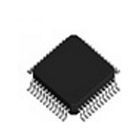
IDTSTAC9758XXTAEB1XR IDT, Integrated Device Technology Inc, IDTSTAC9758XXTAEB1XR Datasheet - Page 35

IDTSTAC9758XXTAEB1XR
Manufacturer Part Number
IDTSTAC9758XXTAEB1XR
Description
IC CODEC AC'97 6CH 2.3 48-TQFP
Manufacturer
IDT, Integrated Device Technology Inc
Type
Audio Codec '97r
Datasheet
1.IDTSTAC9758XXTAEB1XR.pdf
(119 pages)
Specifications of IDTSTAC9758XXTAEB1XR
Data Interface
Serial
Resolution (bits)
20 b
Number Of Adcs / Dacs
2 / 3
Sigma Delta
Yes
Voltage - Supply, Analog
3.14 V ~ 3.47 V; 4.75 V ~ 5.25 V
Voltage - Supply, Digital
3.14 V ~ 3.47 V
Operating Temperature
0°C ~ 70°C
Mounting Type
Surface Mount
Package / Case
48-TQFP, 48-VQFP
Single Supply Voltage (typ)
3.3/5V
Single Supply Voltage (min)
3.135V
Single Supply Voltage (max)
3.465/5.25V
Package Type
TQFP
Lead Free Status / RoHS Status
Lead free / RoHS Compliant
Other names
STAC9758XXTAEB1XR
Available stocks
Company
Part Number
Manufacturer
Quantity
Price
Company:
Part Number:
IDTSTAC9758XXTAEB1XR
Manufacturer:
IDT, Integrated Device Technology Inc
Quantity:
10 000
IDT™
HIGH-PERFORMANCE 6-CHANNEL AC’97 2.3 CODEC WITH UNIVERSAL JACKS™
STAC9758/9759
HIGH-PERFORMANCE 6-CHANNEL AC’97 2.3 CODEC WITH UNIVERSAL JACKS™
5.3.
SDATA_OUT
BIT_CLK
End of previous audio frame
SYNC
AC-Link Output Frame (SDATA_OUT)
The AC-Link output frame data streams correspond to the multiplexed bundles of all digital output
data targeting AC‘97’s DAC inputs, and control registers. As mentioned earlier, each AC-Link output
frame supports up to 12 20-bit outgoing data time slots. Slot 0 is a special reserved time slot contain-
ing 16-bits which are used for AC-Link protocol infrastructure.
Figure 14 illustrates the time slot based AC-Link protocol.
A new AC-Link output frame begins with a low to high transition of SYNC. SYNC is synchronous to
the rising edge of BIT_CLK. On the immediately following falling edge of BIT_CLK, the AC‘97
CODEC samples the assertion of SYNC. This falling edge marks the time when both sides of
AC-Link are aware of the start of a new audio frame. On the next rising of BIT_CLK, the AC‘97 Con-
troller transitions SDATA_OUT into the first bit position of slot 0 (Valid Frame bit). Each new bit posi-
tion is presented to AC-Link on a rising edge of BIT_CLK, and subsequently sampled by the AC‘97
CODEC on the following falling edge of BIT_CLK. This sequence ensures that data transitions and
subsequent sample points for both incoming and outgoing data streams are time aligned.
SDATA_OUT’s composite stream is MSB justified (MSB first) with all non-valid slots’ bit positions
stuffed with 0 by the AC‘97 Controller. If there are less than 20 valid bits within an assigned and valid
time slot, the AC‘97 Controller always stuffs all trailing non-valid bit positions of the 20-bit slot with 0.
As an example, consider an 8-bit sample stream that is being played out to one of the STAC9758/
9759 DACs. The first 8-bit positions are presented to the DAC (MSB justified) followed by the next
12 bit-positions which are stuffed with 0 by the AC‘97 Controller. This ensures that regardless of the
12.288 MHz
Frame
valid
slot1
Tag Phase
S D A T A _ O U T
slot2
("1" = time slot contains valid PCM data)
Time Slot "Valid" Bits
Figure 15. Start of an Audio Output Frame
B I T _ C L K
Figure 14. AC-Link Audio Output Frame
E n d o f p r e v i o u s a u d i o f r a m e
slot(12)
S Y N C
"0"
CID1
CID0
35
1 9
a s s e r t e d
S Y N C
Slot 1
F r a m e
valid
"0"
s l o t 1
S D A T A _ O U T
b i t o f f r a m e
1 9
first
Slot 2
20.8 uS (48 kHZ)
slot2
Data Phase
STAC9758/9759
"0"
1 9
Slot 3
"0"
1 9
PC AUDIO
Slot 12
V 1.2 1206
"0"


