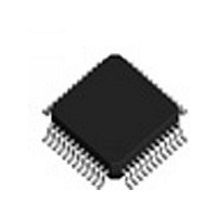
IDTSTAC9758XXTAEB1XR IDT, Integrated Device Technology Inc, IDTSTAC9758XXTAEB1XR Datasheet - Page 5

IDTSTAC9758XXTAEB1XR
Manufacturer Part Number
IDTSTAC9758XXTAEB1XR
Description
IC CODEC AC'97 6CH 2.3 48-TQFP
Manufacturer
IDT, Integrated Device Technology Inc
Type
Audio Codec '97r
Datasheet
1.IDTSTAC9758XXTAEB1XR.pdf
(119 pages)
Specifications of IDTSTAC9758XXTAEB1XR
Data Interface
Serial
Resolution (bits)
20 b
Number Of Adcs / Dacs
2 / 3
Sigma Delta
Yes
Voltage - Supply, Analog
3.14 V ~ 3.47 V; 4.75 V ~ 5.25 V
Voltage - Supply, Digital
3.14 V ~ 3.47 V
Operating Temperature
0°C ~ 70°C
Mounting Type
Surface Mount
Package / Case
48-TQFP, 48-VQFP
Single Supply Voltage (typ)
3.3/5V
Single Supply Voltage (min)
3.135V
Single Supply Voltage (max)
3.465/5.25V
Package Type
TQFP
Lead Free Status / RoHS Status
Lead free / RoHS Compliant
Other names
STAC9758XXTAEB1XR
Available stocks
Company
Part Number
Manufacturer
Quantity
Price
Company:
Part Number:
IDTSTAC9758XXTAEB1XR
Manufacturer:
IDT, Integrated Device Technology Inc
Quantity:
10 000
LIST OF FIGURES
IDT™
HIGH-PERFORMANCE 6-CHANNEL AC’97 2.3 CODEC WITH UNIVERSAL JACKS™
STAC9758/9759
HIGH-PERFORMANCE 6-CHANNEL AC’97 2.3 CODEC WITH UNIVERSAL JACKS™
16. APPENDIX A: PROGRAMMING REGISTERS ................................................................... 116
17. REVISION HISTORY ........................................................................................................... 118
Figure 1. Cold Reset Timing .......................................................................................................................... 17
Figure 2. Warm Reset Timing ........................................................................................................................17
Figure 3. Clocks Timing ................................................................................................................................. 18
Figure 4. Data Setup and Hold Timing .......................................................................................................... 20
Figure 5. Signal Rise and Fall Times Timing ................................................................................................. 20
Figure 6. AC-Link Low Power Mode Timing .................................................................................................. 21
Figure 7. ATE Test Mode Timing ................................................................................................................... 21
Figure 8. Typical Connection Diagram .......................................................................................................... 22
Figure 9. Split Independent Power Supply Operation ................................................................................... 24
Figure 10. AC-Link to its Companion Controller ............................................................................................ 25
Figure 11. CODEC Clock Source Detection .................................................................................................. 26
Figure 12. STAC9758/9759 Powerdown Timing ........................................................................................... 29
Figure 13. Bi-directional AC-Link Frame with Slot assignments .................................................................. 31
Figure 14. AC-Link Audio Output Frame ....................................................................................................... 35
Figure 15. Start of an Audio Output Frame ................................................................................................... 35
Figure 16. STAC9758/9759 Audio Input Frame ........................................................................................... 38
Figure 17. Start of an Audio Input Frame ...................................................................................................... 38
Figure 18. Bi-directional AC-Link Frame with Slot Assignments ................................................................... 43
Figure 19. STAC9758/9759 Mixer Diagram .................................................................................................. 47
Figure 20. Example of STAC9758/9759 Powerdown/Powerup Flow .......................................................... 105
Figure 21. Powerdown/Powerup Flow With Analog Still Active .................................................................. 106
Figure 22. Pin Description Drawing ............................................................................................................. 110
Figure 23. Solder Reflow Profile ................................................................................................................. 114
5
STAC9758/9759
PC AUDIO
V 1.2 1206


