EP3C25F324I7 Altera, EP3C25F324I7 Datasheet - Page 267
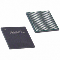
EP3C25F324I7
Manufacturer Part Number
EP3C25F324I7
Description
IC CYCLONE III FPGA 25K 324 FBGA
Manufacturer
Altera
Series
Cyclone® IIIr
Datasheets
1.EP3C5F256C8N.pdf
(5 pages)
2.EP3C5F256C8N.pdf
(34 pages)
3.EP3C5F256C8N.pdf
(66 pages)
4.EP3C5F256C8N.pdf
(14 pages)
5.EP3C5F256C8N.pdf
(76 pages)
6.EP3C25F324I7.pdf
(274 pages)
Specifications of EP3C25F324I7
Number Of Logic Elements/cells
24624
Number Of Labs/clbs
1539
Total Ram Bits
608256
Number Of I /o
215
Voltage - Supply
1.15 V ~ 1.25 V
Mounting Type
Surface Mount
Operating Temperature
-40°C ~ 100°C
Package / Case
324-FBGA
Family Name
Cyclone III
Number Of Logic Blocks/elements
24624
# I/os (max)
215
Frequency (max)
437.5MHz
Process Technology
65nm
Operating Supply Voltage (typ)
1.2V
Logic Cells
24624
Ram Bits
608256
Operating Supply Voltage (min)
1.15V
Operating Supply Voltage (max)
1.25V
Operating Temp Range
-40C to 100C
Operating Temperature Classification
Industrial
Mounting
Surface Mount
Pin Count
324
Package Type
FBGA
For Use With
544-2370 - KIT STARTER CYCLONE III EP3C25
Lead Free Status / RoHS Status
Contains lead / RoHS non-compliant
Number Of Gates
-
Lead Free Status / Rohs Status
Not Compliant
Available stocks
Company
Part Number
Manufacturer
Quantity
Price

Company:
Part Number:
EP3C25F324I7N
Manufacturer:
ALTERA32
Quantity:
181


IEEE Std. 1149.1 BST Architecture
© December 2009
CIII51014-2.2
f
1
Altera Corporation
This chapter provides guidelines on using the IEEE Std. 1149.1 boundary-scan test
(BST) circuitry in Cyclone
BST architecture tests pin connections without using physical test probes, and
captures functional data while a device is operating normally. Boundary-scan cells
(BSCs) in a device can force signals onto pins or capture data from pin or logic array
signals. Forced test data is serially shifted into the boundary-scan cells. Captured data
is serially shifted out and externally compared to expected results.
This chapter contains the following sections:
■
■
■
■
■
Cyclone III device family operating in the IEEE Std. 1149.1 BST mode use four
required pins:
■
■
■
■
The TCK pin has an internal weak pull-down resistor, while the TDI and TMS pins
have weak internal pull-up resistors. The TDO output pin and all the JTAG input pins
are powered by the 2.5-V or 3.0-V V
JTAG configuration.
For recommendations on how to connect a JTAG chain with multiple voltages across
the devices in the chain, refer to
For more information about the description and functionality of all JTAG pins,
registers used by the IEEE Std. 1149.1 BST circuitry, and the test access port (TAP)
controller, refer to
“IEEE Std. 1149.1 BST Architecture” on page 12–1
“IEEE Std. 1149.1 BST Operation Control” on page 12–2
“I/O Voltage Support in a JTAG Chain” on page 12–5
“Guidelines for IEEE Std. 1149.1 BST” on page 12–6
“Boundary-Scan Description Language Support” on page 12–7
TDI
TDO
TMS
TCK
AN39: IEEE 1149.1 (JTAG) Boundary-Scan Testing in Altera
Testing for the Cyclone III Device Family
12. IEEE 1149.1 (JTAG) Boundary-Scan
®
III device family (Cyclone III and Cyclone III LS devices).
“I/O Voltage Support in a JTAG Chain” on page
CCIO
supply. All user I/O pins are tri-stated during
Cyclone III Device Handbook, Volume 1
Devices.
12–5.
Related parts for EP3C25F324I7
Image
Part Number
Description
Manufacturer
Datasheet
Request
R

Part Number:
Description:
CYCLONE II STARTER KIT EP2C20N
Manufacturer:
Altera
Datasheet:


Part Number:
Description:
CPLD, EP610 Family, ECMOS Process, 300 Gates, 16 Macro Cells, 16 Reg., 16 User I/Os, 5V Supply, 35 Speed Grade, 24DIP
Manufacturer:
Altera Corporation
Datasheet:
Part Number:
Description:
CPLD, EP610 Family, ECMOS Process, 300 Gates, 16 Macro Cells, 16 Reg., 16 User I/Os, 5V Supply, 15 Speed Grade, 24DIP
Manufacturer:
Altera Corporation
Datasheet:
Part Number:
Description:
Manufacturer:
Altera Corporation
Datasheet:
Part Number:
Description:
CPLD, EP610 Family, ECMOS Process, 300 Gates, 16 Macro Cells, 16 Reg., 16 User I/Os, 5V Supply, 30 Speed Grade, 24DIP
Manufacturer:
Altera Corporation
Datasheet:
Part Number:
Description:
High-performance, low-power erasable programmable logic devices with 8 macrocells, 10ns
Manufacturer:
Altera Corporation
Datasheet:
Part Number:
Description:
High-performance, low-power erasable programmable logic devices with 8 macrocells, 7ns
Manufacturer:
Altera Corporation
Datasheet:
Part Number:
Description:
Classic EPLD
Manufacturer:
Altera Corporation
Datasheet:
Part Number:
Description:
High-performance, low-power erasable programmable logic devices with 8 macrocells, 10ns
Manufacturer:
Altera Corporation
Datasheet:
Part Number:
Description:
Manufacturer:
Altera Corporation
Datasheet:
Part Number:
Description:
Manufacturer:
Altera Corporation
Datasheet:
Part Number:
Description:
Manufacturer:
Altera Corporation
Datasheet:
Part Number:
Description:
CPLD, EP610 Family, ECMOS Process, 300 Gates, 16 Macro Cells, 16 Reg., 16 User I/Os, 5V Supply, 25 Speed Grade, 24DIP
Manufacturer:
Altera Corporation
Datasheet: