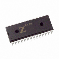
Z84C3006PEG Zilog, Z84C3006PEG Datasheet - Page 46

Z84C3006PEG
Manufacturer Part Number
Z84C3006PEG
Description
IC 6MHZ Z80 CMOS CTC 28-PDIP
Manufacturer
Zilog
Type
Counter/Timer Circuit (CTC)r
Series
Z80r
Specifications of Z84C3006PEG
Frequency
6MHz
Voltage - Supply
4.5 V ~ 5.5 V
Current - Supply
8mA
Operating Temperature
-40°C ~ 100°C
Package / Case
28-DIP (0.600", 15.24mm)
Processor Series
Z84C3xx
Core
Z80
Data Bus Width
8 bit
Maximum Clock Frequency
6 MHz
Operating Supply Voltage
0 V to 5 V
Maximum Operating Temperature
+ 100 C
Mounting Style
Through Hole
Minimum Operating Temperature
- 40 C
Filter Terminals
SMD
Ic Generic Number
84C30
Operating Temperature Min
-40°C
Operating Temperature Max
100°C
Clock Frequency
6MHz
Rohs Compliant
Yes
Cpu Speed
6MHz
Digital Ic Case Style
DIP
No. Of Pins
28
Supply Voltage Range
5V
Operating Temperature Range
-40°C To +100°C
Lead Free Status / RoHS Status
Lead free / RoHS Compliant
Count
-
Lead Free Status / Rohs Status
Details
Other names
269-3910
Z84C3006PEG
Z84C3006PEG
Available stocks
Company
Part Number
Manufacturer
Quantity
Price
Company:
Part Number:
Z84C3006PEG
Manufacturer:
ZILOG
Quantity:
1 980
Company:
Part Number:
Z84C3006PEG
Manufacturer:
Zilog
Quantity:
1 722
Company:
Part Number:
Z84C3006PEG
Manufacturer:
ZILOG
Quantity:
1 980
Company:
Part Number:
Z84C3006PEG
Manufacturer:
WSI
Quantity:
4 970
Part Number:
Z84C3006PEG
Manufacturer:
ZILOG
Quantity:
20 000
- Current page: 46 of 308
- Download datasheet (2Mb)
26
UM008005-0205
Z80 CPU
User’s Manual
Interrupt
Service
Routine
Starting
Address
Table
because the pointer is used to get two adjacent bytes to form a complete 16-
bit service routine starting address and the addresses must always start in
even locations.
Figure 16. Mode 2 Interrupt Response Mode
The first byte in the table is the least-significant (low order portion of the
address). The programmer must complete this table with the correct
addresses before any interrupts are accepted.
The programmer can change this table by storing it in Read/Write Memory,
which also allows individual peripherals to be serviced by different service
routines.
When the interrupting device supplies the lower portion of the pointer, the
CPU automatically pushes the program counter onto the stack, obtains the
starting address from the table, and performs a jump to this address. This
mode of response requires 19 clock periods to complete (seven to fetch the
lower eight bits from the interrupting device, six to save the program
counter, and six to obtain the jump address).
The Z80 peripheral devices include a daisy-chain priority interrupt structure
that automatically supplies the programmed vector to the CPU during
interrupt acknowledge. Refer to the Z80 CPU Peripherals User Manual for
more complete information.
Low Order
High Order
Starting Address
Pointed to by:
I Register
Contents
Seven Bits From
Peripheral
0
Overview
Related parts for Z84C3006PEG
Image
Part Number
Description
Manufacturer
Datasheet
Request
R

Part Number:
Description:
Communication Controllers, ZILOG INTELLIGENT PERIPHERAL CONTROLLER (ZIP)
Manufacturer:
Zilog, Inc.
Datasheet:

Part Number:
Description:
KIT DEV FOR Z8 ENCORE 16K TO 64K
Manufacturer:
Zilog
Datasheet:

Part Number:
Description:
KIT DEV Z8 ENCORE XP 28-PIN
Manufacturer:
Zilog
Datasheet:

Part Number:
Description:
DEV KIT FOR Z8 ENCORE 8K/4K
Manufacturer:
Zilog
Datasheet:

Part Number:
Description:
KIT DEV Z8 ENCORE XP 28-PIN
Manufacturer:
Zilog
Datasheet:

Part Number:
Description:
DEV KIT FOR Z8 ENCORE 4K TO 8K
Manufacturer:
Zilog
Datasheet:

Part Number:
Description:
CMOS Z8 microcontroller. ROM 16 Kbytes, RAM 256 bytes, speed 16 MHz, 32 lines I/O, 3.0V to 5.5V
Manufacturer:
Zilog, Inc.
Datasheet:

Part Number:
Description:
Low-cost microcontroller. 512 bytes ROM, 61 bytes RAM, 8 MHz
Manufacturer:
Zilog, Inc.
Datasheet:

Part Number:
Description:
Z8 4K OTP Microcontroller
Manufacturer:
Zilog, Inc.
Datasheet:

Part Number:
Description:
CMOS SUPER8 ROMLESS MCU
Manufacturer:
Zilog, Inc.
Datasheet:

Part Number:
Description:
SL1866 CMOSZ8 OTP Microcontroller
Manufacturer:
Zilog, Inc.
Datasheet:

Part Number:
Description:
SL1866 CMOSZ8 OTP Microcontroller
Manufacturer:
Zilog, Inc.
Datasheet:

Part Number:
Description:
OTP (KB) = 1, RAM = 125, Speed = 12, I/O = 14, 8-bit Timers = 2, Comm Interfaces Other Features = Por, LV Protect, Voltage = 4.5-5.5V
Manufacturer:
Zilog, Inc.
Datasheet:

Part Number:
Description:
Manufacturer:
Zilog, Inc.
Datasheet:


