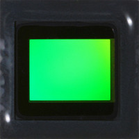
MT9P401I12STC Aptina LLC, MT9P401I12STC Datasheet - Page 52

MT9P401I12STC
Manufacturer Part Number
MT9P401I12STC
Description
SENSOR IMAGE CMOS 5MP 48LCC
Manufacturer
Aptina LLC
Type
CMOS Imagingr
Series
DigitalClarity®r
Specifications of MT9P401I12STC
Pixel Size
2.2µm x 2.2µm
Active Pixel Array
2592H x 1944V
Frames Per Second
60
Voltage - Supply
2.6 V ~ 3.1 V
Package / Case
48-iLCC
Sensor Image Color Type
Monochrome
Sensor Image Size
2592x1944Pixels
Operating Supply Voltage (typ)
1.8/2.8V
Operating Supply Voltage (max)
3.1V
Operating Temp Range
-30C to 70C
Package Type
ILCC
Operating Temperature Classification
Commercial
Mounting
Surface Mount
Pin Count
48
Lead Free Status / RoHS Status
Lead free / RoHS Compliant
Other names
557-1263
MT9P401I12STC
Q3412742
MT9P401I12STC
Q3412742
Available stocks
Company
Part Number
Manufacturer
Quantity
Price
Part Number:
MT9P401I12STC
Manufacturer:
APTINA
Quantity:
20 000
Digital Black Level Calibration
Test Patterns
Table 18:
PDF: 09005aef82acb06f/Source: 09005aef81a4a477
MT9P401_DS_2 - Rev. B 9/07 EN
Test Pattern Modes
Black level calibration is normally done separately for each color channel, and different
channels can be using different sample or adjustment methods at the same time.
However, because both Green1 and Green2 pixels go through the same signal chain, and
Red and Blue pixels likewise go through the same signal chain, it is expected that the
chosen offset for these pairs should be the same as long as the gains are the same. If
Lock_Green_Calibration is set, and (Green1_Analog_Gain = Green2_Analog_Gain) and
(Green1_Analog_Multiplier = Green2_Analog_Multiplier), the calculated or user-speci-
fied Green1_Offset is used for both green channels. Similarly, if Lock_Red/
Blue_Calibration is set, and (Red_Analog_Gain = Blue_Analog_Gain) and
(Red_Analog_Multiplier = Blue_Analog_Multiplier), the calculated or user-specified
Red_Offset is used for both the red and blue channels.
The current values of the offsets can be read from the Green1_Offset, Red_Offset,
Blue_Offset, and Green2_Offset registers. Writes to these registers when Manual_BLC is
set change the offsets being used. In automatic BLC mode, writes to these registers are
effective when manual mode is re-entered. In Manual_BLC mode, no sampling or
adjusting takes place for any color.
Digital black level calibration is the final calculation applied to pixel data before it is
output. It provides a precise black level to complement the coarser-grained analog black
level calibration, and also corrects for black level shift introduced by digital gain. This
correction applies to the active columns for all rows, including dark rows.
The MT9P401 has the capability of injecting a number of test patterns into the top of the
datapath to debug the digital logic. With one of the test patterns activated, any of the
datapath functions can be enabled to exercise it in a deterministic fashion. Test patterns
are enabled when Enable_Test_Pattern is set. Only one of the test patterns can be
enabled at a given point in time by setting the Test_Pattern_Mode register according to
Table 18. When test patterns are enabled the active area will receive the value specified
by the selected test pattern and the dark pixels will receive the value in
Test_Pattern_Green for green pixels, Test_Pattern_Blue for blue pixels, and
Test_Pattern_Red for red pixels.
Test_Pattern_Mode
Micron Confidential and Proprietary
0
1
2
3
4
5
6
7
8
MT9P401: 1/2.5-Inch 5Mp Digital Image Sensor
52
Micron Technology, Inc., reserves the right to change products or specifications without notice.
Color field (normal operation)
Monochrome horizontal bars
Monochrome vertical bars
Test Pattern Output
Horizontal gradient
Classic test pattern
Diagonal gradient
Vertical color bars
Vertical gradient
Walking 1s
©2007 Micron Technology, Inc. All rights reserved.
Features


