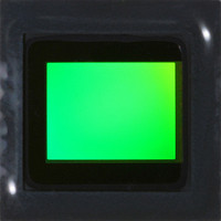
MT9P401I12STC Aptina LLC, MT9P401I12STC Datasheet - Page 49

MT9P401I12STC
Manufacturer Part Number
MT9P401I12STC
Description
SENSOR IMAGE CMOS 5MP 48LCC
Manufacturer
Aptina LLC
Type
CMOS Imagingr
Series
DigitalClarity®r
Specifications of MT9P401I12STC
Pixel Size
2.2µm x 2.2µm
Active Pixel Array
2592H x 1944V
Frames Per Second
60
Voltage - Supply
2.6 V ~ 3.1 V
Package / Case
48-iLCC
Sensor Image Color Type
Monochrome
Sensor Image Size
2592x1944Pixels
Operating Supply Voltage (typ)
1.8/2.8V
Operating Supply Voltage (max)
3.1V
Operating Temp Range
-30C to 70C
Package Type
ILCC
Operating Temperature Classification
Commercial
Mounting
Surface Mount
Pin Count
48
Lead Free Status / RoHS Status
Lead free / RoHS Compliant
Other names
557-1263
MT9P401I12STC
Q3412742
MT9P401I12STC
Q3412742
Available stocks
Company
Part Number
Manufacturer
Quantity
Price
Part Number:
MT9P401I12STC
Manufacturer:
APTINA
Quantity:
20 000
Figure 24:
Strobe Control
Table 16:
PDF: 09005aef82acb06f/Source: 09005aef81a4a477
MT9P401_DS_2 - Rev. B 9/07 EN
STROBE Timepoints
GRR Snapshot Timing
To support synchronization of the exposure with external events such as a flash or
mechanical shutter, the MT9P401 produces a STROBE output. By default, this signal is
asserted for approximately the time that all rows are simultaneously exposing, minus
the vertical blanking time, as shown in Figure 23 on page 48 and Figure 24. Also indi-
cated in these figures are the leading and trailing edges of STROBE, which an be config-
ured to occur at one of several timepoints. The leading edge of STROBE occurs at
STROBE_Start, and the trailing edge at STROBE_End, which are set to codes described in
Table 16.
If STROBE_Start and STROBE_End are set to the same timepoint, the strobe is a
wide pulse starting at the STROBE_Start timepoint. If the settings are such that the
strobe would occur after the trailing edge of FV, the strobe may be only
Symbol
(b) GRR Bulb
(a) GRR Snapshot
TSW
TT1
TT2
TSE
TRIGGER
TRIGGER
STROBE
STROBE
D
D
OUT
OUT
FV
LV
FV
LV
Micron Confidential and Proprietary
Timepoint
Trigger 1 (start of shutter scan)
Start of exposure (all rows simultaneously exposing) offset by VB
End of shutter width (expiration of the internal shutter width
counter)
Trigger 2 (start of readout scan)
TT1
TT1
VB x t ROW + 2000 x t ACLK
VB x t ROW + 2000 x t ACLK
MT9P401: 1/2.5-Inch 5Mp Digital Image Sensor
49
SW x t ROW + 2000 x t ACLK
SW x t ROW + 2000 x t ACLK
Micron Technology, Inc., reserves the right to change products or specifications without notice.
First Row Exposure
First Row Exposure
Second Row Exposure
Second Row Exposure
TSE
TSE
TSW TT2
©2007 Micron Technology, Inc. All rights reserved.
TSW
TT2
8 x t ROW
8 x t ROW
t
ACLK wide;
t ROW
t ROW
Features
Code
t
ROW
1
2
3
–


