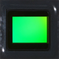
MT9P401I12STC Aptina LLC, MT9P401I12STC Datasheet - Page 46

MT9P401I12STC
Manufacturer Part Number
MT9P401I12STC
Description
SENSOR IMAGE CMOS 5MP 48LCC
Manufacturer
Aptina LLC
Type
CMOS Imagingr
Series
DigitalClarity®r
Specifications of MT9P401I12STC
Pixel Size
2.2µm x 2.2µm
Active Pixel Array
2592H x 1944V
Frames Per Second
60
Voltage - Supply
2.6 V ~ 3.1 V
Package / Case
48-iLCC
Sensor Image Color Type
Monochrome
Sensor Image Size
2592x1944Pixels
Operating Supply Voltage (typ)
1.8/2.8V
Operating Supply Voltage (max)
3.1V
Operating Temp Range
-30C to 70C
Package Type
ILCC
Operating Temperature Classification
Commercial
Mounting
Surface Mount
Pin Count
48
Lead Free Status / RoHS Status
Lead free / RoHS Compliant
Other names
557-1263
MT9P401I12STC
Q3412742
MT9P401I12STC
Q3412742
Available stocks
Company
Part Number
Manufacturer
Quantity
Price
Part Number:
MT9P401I12STC
Manufacturer:
APTINA
Quantity:
20 000
Image Acquisition Modes
Electronic Rolling Shutter
Global Reset Release
Exposure
PDF: 09005aef82acb06f/Source: 09005aef81a4a477
MT9P401_DS_2 - Rev. B 9/07 EN
The MT9P401 supports two image acquisition modes (Shutter Types) (see “Operating
Modes” on page 47), electronic rolling shutter and global reset release.
The ERS modes take pictures by scanning the rows of the sensor twice in the order
described in “Full-Array Readout” on page 38. On the first scan, each row is released
from reset, starting the exposure. On the second scan, the row is sampled, processed,
and returned to the reset state. The exposure for any row is therefore the time between
the first and second scans. Each row is exposed for the same duration, but at slightly
different point in time, which can cause a shear in moving subjects.
Whenever the mode is changed to an ERS mode (even from another ERS mode), and
before the first frame following reset, there is an anti-blooming sequence where all rows
are placed in reset. This sequence must complete before continuous readout begins.
This delay is:
The GRR modes attempt to address the shearing effect by starting all rows' exposures at
the same time. Instead of the first scan used in ERS mode, the reset to each row is
released simultaneously. The second scan occurs as normal, so the exposure time for
each row would different. Typically, an external mechanical shutter would be used to
stop the exposure of all rows simultaneously.
In GRR modes, there is a startup overhead before each frame as all rows are initially
placed in the reset state (
each frame. However, it occurs as soon as possible after the preceding frame, so typically
the time from trigger to the start of exposure does not include this delay. To ensure that
this is the case, the first trigger must occur no sooner than
frame is read out.
The nominal exposure time,
defined by the shutter width, SW, and the shutter overhead, SO, which includes the
effect of Shutter_Delay. Exposure time for other modes is defined relative to this time.
Increasing Shutter_Delay (SD) decreases the exposure time. Exposure times are typically
specified in units of row time, although it is possible to fine-tune exposures in units of
t
t
where:
SW = max(1, (2 * 16 × Shutter_Width_Upper) + Shutter_Width_Lower)
SO = 208 × (Row_Bin + 1) + 98 + min(SD, SDmax) – 94
SD = Shutter_Delay + 1
SDmax = 1232; if SW < 3
ACLKs (where
EXP = SW ×
t
ALLRESET = 16 × 2004 ×
1504, otherwise
t
ROW – SO × 2 ×
Micron Confidential and Proprietary
t
ACLK is 2 *
t
ALLRESET). Unlike ERS mode, this delay always occurs before
t
MT9P401: 1/2.5-Inch 5Mp Digital Image Sensor
PIXCLK).
t
ACLK
t
t
EXP , is the effective shutter time in ERS modes, and is
46
PIXCLK
Micron Technology, Inc., reserves the right to change products or specifications without notice.
t
ALLRESET after the previous
©2007 Micron Technology, Inc. All rights reserved.
Features


