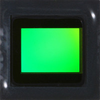
MT9P401I12STC Aptina LLC, MT9P401I12STC Datasheet - Page 50

MT9P401I12STC
Manufacturer Part Number
MT9P401I12STC
Description
SENSOR IMAGE CMOS 5MP 48LCC
Manufacturer
Aptina LLC
Type
CMOS Imagingr
Series
DigitalClarity®r
Specifications of MT9P401I12STC
Pixel Size
2.2µm x 2.2µm
Active Pixel Array
2592H x 1944V
Frames Per Second
60
Voltage - Supply
2.6 V ~ 3.1 V
Package / Case
48-iLCC
Sensor Image Color Type
Monochrome
Sensor Image Size
2592x1944Pixels
Operating Supply Voltage (typ)
1.8/2.8V
Operating Supply Voltage (max)
3.1V
Operating Temp Range
-30C to 70C
Package Type
ILCC
Operating Temperature Classification
Commercial
Mounting
Surface Mount
Pin Count
48
Lead Free Status / RoHS Status
Lead free / RoHS Compliant
Other names
557-1263
MT9P401I12STC
Q3412742
MT9P401I12STC
Q3412742
Available stocks
Company
Part Number
Manufacturer
Quantity
Price
Part Number:
MT9P401I12STC
Manufacturer:
APTINA
Quantity:
20 000
Signal Chain and Datapath
Figure 25:
Gain
Table 17:
Analog Gain
PDF: 09005aef82acb06f/Source: 09005aef81a4a477
MT9P401_DS_2 - Rev. B 9/07 EN
Gain Range
4.25–8
9–128
1– 4
Gain Increment Settings
Signal Path
Note:
however, because there is no concept of a row at that time. The sense of the STROBE
signal can be inverted by setting Invert_Strobe (R0x1E[5] = 1. To use strobe as a flash in
snapshot modes or with mechanical shutter, set the Strobe_Enable register bit field
R0x1E[4] = 1.
The signal chain and datapath are shown in Figure 25. Each color is processed indepen-
dently, including separate gain and offset settings. Voltages sampled from the pixel array
are first passed through an analog gain stage, which can produce gain factors between 1
and 8. An analog offset is then applied, and the signal is sent through a 12-bit analog-to-
digital converter. In the digital space, a digital gain factor of between 1 and 16 is applied,
and then a digital offset of between –2048 and 2047 is added. The resulting 12-bit pixel
value is then output on the D
The analog offset applied is determined automatically by the black level calibration
algorithm, which attempts to shift the output of the analog signal chain so that black is
at a particular level. The digital offset is a fine-tuning of the analog offset.
There are two types of gain supported: analog gain and digital gain. Combined, gains of
between 1 and 128 are possible. The recommended gain settings are shown in Table 17.
The combined gain for a color C is given by:
G
The analog gain is specified independently for each color channel. There are two
components, the gain and the multiplier. The gain is specified by Green1_Analog_Gain,
Red_Analog_Gain, Blue_Analog_Gain, and Green2_Analog_Gain in steps of 0.125. The
Voltage
C
Increments
= AG
Pixel
Analog gain should be maximized before applying digital gain.
0.125
0.25
1
C
x DG
Analog
Gain
Micron Confidential and Proprietary
C
X
.
Analog
Offset
Digital Gain
+
MT9P401: 1/2.5-Inch 5Mp Digital Image Sensor
1–120
OUT
Analog Signal Chain
50
0
0
[11:0] ports.
Micron Technology, Inc., reserves the right to change products or specifications without notice.
ADC
Analog Multipier
Digital Datapath
Calibration
Black
Level
0
1
1
Digital
Gain
©2007 Micron Technology, Inc. All rights reserved.
X
Correction
Digital
Offset
Analog Gain
+
17–32
8–32
32
Features
D
OUT
[11: 0]


