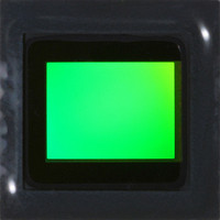
MT9P401I12STC Aptina LLC, MT9P401I12STC Datasheet - Page 43

MT9P401I12STC
Manufacturer Part Number
MT9P401I12STC
Description
SENSOR IMAGE CMOS 5MP 48LCC
Manufacturer
Aptina LLC
Type
CMOS Imagingr
Series
DigitalClarity®r
Specifications of MT9P401I12STC
Pixel Size
2.2µm x 2.2µm
Active Pixel Array
2592H x 1944V
Frames Per Second
60
Voltage - Supply
2.6 V ~ 3.1 V
Package / Case
48-iLCC
Sensor Image Color Type
Monochrome
Sensor Image Size
2592x1944Pixels
Operating Supply Voltage (typ)
1.8/2.8V
Operating Supply Voltage (max)
3.1V
Operating Temp Range
-30C to 70C
Package Type
ILCC
Operating Temperature Classification
Commercial
Mounting
Surface Mount
Pin Count
48
Lead Free Status / RoHS Status
Lead free / RoHS Compliant
Other names
557-1263
MT9P401I12STC
Q3412742
MT9P401I12STC
Q3412742
Available stocks
Company
Part Number
Manufacturer
Quantity
Price
Part Number:
MT9P401I12STC
Manufacturer:
APTINA
Quantity:
20 000
Mirror
Column Mirror Image
Figure 21:
Row Mirror Image
Figure 22:
PDF: 09005aef82acb06f/Source: 09005aef81a4a477
MT9P401_DS_2 - Rev. B 9/07 EN
Six Pixels in Normal and Column Mirror Readout Modes
Six Rows in Normal and Row Mirror Readout Modes
By setting R0x20[14] = 1, the readout order of the columns is reversed, as shown in
Figure 21. The starting color, thus Bayer pattern, is preserved when mirroring the
columns.
By setting R0x20[15] = 1, the readout order of the rows is reversed as shown in Figure 22.
The starting color, thus Bayer pattern, is preserved when mirroring the rows.
Reverse readout
By default, active pixels in the resulting image are output in row-major order (an entire
row is output before the next row is begun), from lowest row/column number to
highest. If desired, the output (and sampling) order of the rows and columns can be
reversed. This affects only pixels in the active region defined above, not any pixels read
out as dark rows or dark columns. When the readout direction is reversed, the color
order is reversed as well (red, green, red, and so on, instead of green, red, green, and so
on, for example).
If row binning is combined with row mirroring, the binning is still done in the positive
direction. Therefore, if the first output row in bin 2X + row mirror was 1997, pixels on
rows 1997 and 1999 would be averaged together. The next pixel output would be from
rows 1996 and 1998, followed by the average of 1993 and 1995.
For column mirroring plus binning, the span of pixels used should be the same as with
non-mirror mode.
Normal readout
Reverse readout
Normal readout
D
D
D
D
OUT
OUT
OUT
OUT
[11:0]
[11:0]
[11:0]
[11:0]
FV
LV
Micron Confidential and Proprietary
Row0 [11:0] Row1 [11:0] Row2 [11:0] Row3 [11:0] Row4 [11:0] Row5 [11:0]
Row5 [11:0] Row4 [11:0] Row3 [11:0] Row2 [11:0] Row1 [11:0] Row0 [11:0]
G0[11:0] R0[11:0] G1[11:0] R1[11:0] G2[11:0] R2[11:0]
R2[11:0] G2[11:0] R1[11:0] G1[11:0] R0[11:0] G0[11:0]
MT9P401: 1/2.5-Inch 5Mp Digital Image Sensor
43
Micron Technology, Inc., reserves the right to change products or specifications without notice.
©2007 Micron Technology, Inc. All rights reserved.
Features


