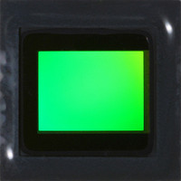
MT9P401I12STC Aptina LLC, MT9P401I12STC Datasheet - Page 36

MT9P401I12STC
Manufacturer Part Number
MT9P401I12STC
Description
SENSOR IMAGE CMOS 5MP 48LCC
Manufacturer
Aptina LLC
Type
CMOS Imagingr
Series
DigitalClarity®r
Specifications of MT9P401I12STC
Pixel Size
2.2µm x 2.2µm
Active Pixel Array
2592H x 1944V
Frames Per Second
60
Voltage - Supply
2.6 V ~ 3.1 V
Package / Case
48-iLCC
Sensor Image Color Type
Monochrome
Sensor Image Size
2592x1944Pixels
Operating Supply Voltage (typ)
1.8/2.8V
Operating Supply Voltage (max)
3.1V
Operating Temp Range
-30C to 70C
Package Type
ILCC
Operating Temperature Classification
Commercial
Mounting
Surface Mount
Pin Count
48
Lead Free Status / RoHS Status
Lead free / RoHS Compliant
Other names
557-1263
MT9P401I12STC
Q3412742
MT9P401I12STC
Q3412742
Available stocks
Company
Part Number
Manufacturer
Quantity
Price
Part Number:
MT9P401I12STC
Manufacturer:
APTINA
Quantity:
20 000
Features
Reset
Hard Reset
Soft Reset
Power Up and Power Down
Clocks
PDF: 09005aef82acb06f/Source: 09005aef81a4a477
MT9P401_DS_2 - Rev. B 9/07 EN
1. Ensure RESET_BAR is asserted (LOW).
2. Bring up the supplies. If both the analog and the digital supplies cannot be brought
3. Negate RESET_BAR (HIGH) to bring up the sensor.
1. Assert RESET_BAR.
2. Remove the supplies.
The MT9P401 may be reset by using RESET_BAR (active LOW) or the reset register.
Assert (LOW) RESET_BAR, it is not necessary to clock the device. All registers return to
the factory defaults. When the pin is negated (HIGH), the chip resumes normal opera-
tion.
Set the Reset register field to “1” (R0x0D[0] = 1). All registers except the following will be
reset:
• Chip_Enable
• Synchronize_Changes
• Reset
• Use_PLL
• Power_PLL
• PLL_m_Factor
• PLL_n_Divider
• PLL_p1_Divider
When the field is returned to “0,” the chip resumes normal operation.
When first powering on the MT9P401, follow this sequence:
When powering down, be sure to follow this sequence to ensure that I/Os do not load
any buses that they are connected to.
The MT9P401 requires one clock (EXTCLK), which is nominally 96 MHz. By default, this
results in pixels being output on the D
V
48 Mp/s, respectively. The EXTCLK clock can be divided down internally by setting
Divide_Pixel_Clock to a non-zero value. This slows down the operation of the chip as
though EXTCLK had been divided externally.
f
PIXCLK= {
DD
up simultaneously, ensure the digital supply comes up first.
_IO = 1.8V, maximum master clock and maximum data rate become 48 MHz and
Micron Confidential and Proprietary
f
f
EXTCLK
EXTCLK / (2 × Divide_Pixel_Clock)
MT9P401: 1/2.5-Inch 5Mp Digital Image Sensor
36
OUT
Micron Technology, Inc., reserves the right to change products or specifications without notice.
pins at a maximum data rate of 96 Mp/s. With
if Divide_Pixel_Clock = 0
otherwise
©2007 Micron Technology, Inc. All rights reserved.
Features


