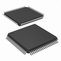
ADUC7126BSTZ126-RL Analog Devices Inc, ADUC7126BSTZ126-RL Datasheet - Page 72

ADUC7126BSTZ126-RL
Manufacturer Part Number
ADUC7126BSTZ126-RL
Description
ARM7 With 12-Bit ADC & DACs, 128kB Flash
Manufacturer
Analog Devices Inc
Series
MicroConverter® ADuC7xxxr
Datasheet
1.ADUC7126BSTZ126.pdf
(104 pages)
Specifications of ADUC7126BSTZ126-RL
Core Processor
ARM7
Core Size
16/32-Bit
Speed
41.78MHz
Connectivity
EBI/EMI, I²C, SPI, UART/USART
Peripherals
POR, PWM, WDT
Number Of I /o
40
Program Memory Size
126KB (126K x 8)
Program Memory Type
FLASH
Ram Size
32K x 8
Voltage - Supply (vcc/vdd)
2.7 V ~ 3.6 V
Data Converters
A/D 12x12b, D/A 4x12b
Oscillator Type
Internal
Operating Temperature
-40°C ~ 125°C
Package / Case
80-LQFP
Lead Free Status / RoHS Status
Lead free / RoHS Compliant
Eeprom Size
-
Lead Free Status / RoHS Status
Lead free / RoHS Compliant
Available stocks
Company
Part Number
Manufacturer
Quantity
Price
Company:
Part Number:
ADUC7126BSTZ126-RL
Manufacturer:
Analog Devices Inc
Quantity:
10 000
ADuC7124/ADuC7126
I
Name:
Address:
Default Value:
Access:
Function:
Table 103. I2CxMSTA MMR Bit Descriptions
Bit
[15:11]
10
9
8
7
6
5
4
3
2
[1:0]
2
C Master Status Register
Name
I2CBBUSY
I2CMRxFO
I2CMTC
I2CMNA
I2CMBUSY
I2CAL
I2CMNA
I2CMRXQ
I2CMTXQ
I2CMTFSTA
I2C0MSTA, I2C1MSTA
0xFFFF0804, 0xFFFF0904
0x0000, 0x0000
Read only
This 16-bit MMR is the I
Description
Reserved.
I
This bit is set to 1 when a start condition is detected on the I
This bit is cleared when a stop condition is detected on the bus.
Master Rx FIFO overflow.
This bit is set to 1 when a byte is written to the Rx FIFO when it is already full.
This bit is cleared in all other conditions.
I
This bit is set to 1 when a transmission is complete between the master and the slave it was
communicating with.
If the I2CMCENI bit in I2CxMCON is set, an interrupt is generated when this bit is set.
Clear this bit to clear the interrupt source.
I
This bit is set to 1 when a NACK condition is received by the master in response to a data write transfer.
If the I2CNACKENI bit in I2CxMCON is set, an interrupt is generated when this bit is set.
This bit is cleared in all other conditions.
I
Set to 1 when the master is busy processing a transaction.
Cleared if the master is ready or if another master device has control of the bus.
I
This bit is set to 1 when the I
If the I2CALENI bit in I2CxMCON is set, an interrupt is generated when this bit is set.
This bit is cleared in all other conditions.
I
This bit is set to 1 when a NACK condition is received by the master in response to an address.
If the I2CNACKENI bit in I2CxMCON is set, an interrupt is generated when this bit is set.
This bit is cleared in all other conditions.
I
This bit is set to 1 when data enters the Rx FIFO. If the I2CMRENI in I2CxMCON is set, an interrupt is
generated.
This bit is cleared in all other conditions.
I
This bit goes high if the Tx FIFO is empty or contains only one byte and the master has transmitted an
address + write. If the I2CMTENI bit in I2CxMCON is set, an interrupt is generated when this bit is set.
This bit is cleared in all other conditions.
I
00 = I
01 = one byte in master Tx FIFO.
10 = one byte in master Tx FIFO.
11 = I
2
2
2
2
2
2
2
2
2
C bus busy status bit.
C transmission complete status bit.
C master NACK data bit.
C master busy status bit.
C arbitration lost status bit.
C master NACK address bit.
C master receive request bit.
C master transmit request bit.
C master Tx FIFO status bits.
2
2
C master Tx FIFO empty.
C master Tx FIFO full.
2
C status register in master mode.
Rev. B | Page 72 of 104
2
C master is unable to gain control of the I
2
C bus.
2
C bus.


