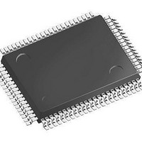
SAF-XC164CS-32F40F BB-A Infineon Technologies, SAF-XC164CS-32F40F BB-A Datasheet - Page 70

SAF-XC164CS-32F40F BB-A
Manufacturer Part Number
SAF-XC164CS-32F40F BB-A
Description
IC MCU 16BIT 256KB FLSH 100TQFP
Manufacturer
Infineon Technologies
Series
XC16xr
Datasheet
1.SAK-XC164CS-32F20F_BB-A.pdf
(81 pages)
Specifications of SAF-XC164CS-32F40F BB-A
Core Processor
C166SV2
Core Size
16-Bit
Speed
40MHz
Connectivity
CAN, EBI/EMI, SPI, UART/USART
Peripherals
PWM, WDT
Number Of I /o
79
Program Memory Size
256KB (256K x 8)
Program Memory Type
FLASH
Ram Size
12K x 8
Voltage - Supply (vcc/vdd)
2.35 V ~ 2.7 V
Data Converters
A/D 14x8/10b
Oscillator Type
Internal
Operating Temperature
-40°C ~ 85°C
Package / Case
100-LFQFP
Data Bus Width
16 bit
Data Ram Size
12 KB
Interface Type
2xASC, 2xSSC
Maximum Clock Frequency
40 MHz
Number Of Programmable I/os
79
Number Of Timers
11
Operating Supply Voltage
5 V
Maximum Operating Temperature
+ 85 C
Mounting Style
SMD/SMT
Minimum Operating Temperature
- 40 C
On-chip Adc
10 bit, 14 Channel
Packages
PG-TQFP-100
Max Clock Frequency
40.0 MHz
Sram (incl. Cache)
12.0 KByte
Can Nodes
2
A / D Input Lines (incl. Fadc)
14
Program Memory
256.0 KByte
Lead Free Status / RoHS Status
Lead free / RoHS Compliant
Eeprom Size
-
Lead Free Status / Rohs Status
Details
4.4.3
Table 19
Parameter
Oscillator period
High time
Low time
Rise time
Fall time
1) The maximum limit is only relevant for PLL operation to ensure the minimum input frequency for the PLL.
2) The clock input signal must reach the defined levels
Figure 17
Note: If the on-chip oscillator is used together with a crystal or a ceramic resonator, the
Data Sheet
oscillator frequency is limited to a range of 4 MHz to 16 MHz.
It is strongly recommended to measure the oscillation allowance (negative
resistance) in the final target system (layout) to determine the optimum
parameters for the oscillator operation. Please refer to the limits specified by the
crystal supplier.
When driven by an external clock signal it will accept the specified frequency
range. Operation at lower input frequencies is possible but is verified by design
only (not subject to production test).
2)
2)
2)
2)
External Clock Drive XTAL1
0.5
External Clock Drive Characteristics (Operating Conditions apply)
External Clock Drive XTAL1
V
DDI
t
1
t
2
68
Symbol
t
t
t
t
t
OSC
1
2
3
4
V
ILC
t
and
OSC
t
3
SR
SR
SR
SR
SR
V
IHC
.
Min.
25
6
6
–
–
Limit Values
t
4
Electrical Parameters
MCT05572
Max.
250
–
–
8
8
V
V
1)
IHC
ILC
Derivatives
V1.1, 2006-08
XC164-32
Unit
ns
ns
ns
ns
ns


