SAF-XC164CS-32F40F BB-A Infineon Technologies, SAF-XC164CS-32F40F BB-A Datasheet - Page 66
SAF-XC164CS-32F40F BB-A
Manufacturer Part Number
SAF-XC164CS-32F40F BB-A
Description
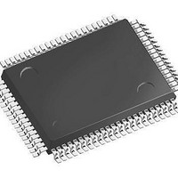
IC MCU 16BIT 256KB FLSH 100TQFP
Manufacturer
Infineon Technologies
Series
XC16xr
Datasheet
1.SAK-XC164CS-32F20F_BB-A.pdf
(81 pages)
Specifications of SAF-XC164CS-32F40F BB-A
Core Processor
C166SV2
Core Size
16-Bit
Speed
40MHz
Connectivity
CAN, EBI/EMI, SPI, UART/USART
Peripherals
PWM, WDT
Number Of I /o
79
Program Memory Size
256KB (256K x 8)
Program Memory Type
FLASH
Ram Size
12K x 8
Voltage - Supply (vcc/vdd)
2.35 V ~ 2.7 V
Data Converters
A/D 14x8/10b
Oscillator Type
Internal
Operating Temperature
-40°C ~ 85°C
Package / Case
100-LFQFP
Data Bus Width
16 bit
Data Ram Size
12 KB
Interface Type
2xASC, 2xSSC
Maximum Clock Frequency
40 MHz
Number Of Programmable I/os
79
Number Of Timers
11
Operating Supply Voltage
5 V
Maximum Operating Temperature
+ 85 C
Mounting Style
SMD/SMT
Minimum Operating Temperature
- 40 C
On-chip Adc
10 bit, 14 Channel
Packages
PG-TQFP-100
Max Clock Frequency
40.0 MHz
Sram (incl. Cache)
12.0 KByte
Can Nodes
2
A / D Input Lines (incl. Fadc)
14
Program Memory
256.0 KByte
Lead Free Status / RoHS Status
Lead free / RoHS Compliant
Eeprom Size
-
Lead Free Status / Rohs Status
Details


CPU and EBC are clocked with the CPU clock signal
same frequency as the master clock (
two:
The specification of the external timing (AC Characteristics) depends on the period of the
CPU clock, called “TCP”.
The other peripherals are supplied with the system clock signal
frequency as the CPU clock signal
Bypass Operation
When bypass operation is configured (PLLCTRL = 0x
the internal oscillator (input clock signal XTAL1) through the input- and output-
prescalers:
f
If both divider factors are selected as ‘1’ (PLLIDIV = PLLODIV = ‘0’) the frequency of
directly follows the frequency of
cycle of the input clock
The lowest master clock frequency is achieved by selecting the maximum values for both
divider factors:
f
Phase Locked Loop (PLL)
When PLL operation is configured (PLLCTRL = 11
enabled and provides the master clock. The PLL multiplies the input frequency by the
factor F (
the output divider (F = PLLMUL+1 / (PLLIDIV+1 × PLLODIV+1)). The PLL circuit
synchronizes the master clock to the input clock. This synchronization is done smoothly,
i.e. the master clock frequency does not change abruptly.
Due to this adaptation to the input clock the frequency of
is locked to
of individual TCMs.
The timing listed in the AC Characteristics refers to TCPs. Because
f
circumstances.
The actual minimum value for TCP depends on the jitter of the PLL. As the PLL is
constantly adjusting its output frequency so it corresponds to the applied input frequency
(crystal or oscillator) the relative deviation for periods of more than one TCP is lower than
for one single TCP (see formula and
This is especially important for bus cycles using waitstates and e.g. for the operation of
timers, serial interfaces, etc. For all slower operations and longer periods (e.g. pulse train
Data Sheet
MC
MC
MC
, the timing must be calculated using the minimum TCP possible under the respective
=
=
f
CPU
f
f
OSC
OSC
f
=
MC
/ ((PLLIDIV+1) × (PLLODIV+1)).
/ ((3 + 1) × (14 + 1)) =
f
f
MC
OSC
=
f
/ 2. This factor is selected by bit CPSYS in register SYSCON1.
OSC
. The slight variation causes a jitter of
× F) which results from the input divider, the multiplication factor, and
f
OSC
.
f
OSC
f
OSC
f
CPU
so the high and low time of
Figure
/ 60.
f
CPU
.
64
=
16).
f
MC
) or can be the master clock divided by
B
) the on-chip phase locked loop is
B
f
f
MC
CPU
) the master clock is derived from
which also affects the duration
f
. The CPU clock can have the
MC
is constantly adjusted so it
f
f
MC
SYS
Electrical Parameters
is defined by the duty
which has the same
f
CPU
is derived from
Derivatives
V1.1, 2006-08
XC164-32
f
MC
Related parts for SAF-XC164CS-32F40F BB-A
Image
Part Number
Description
Manufacturer
Datasheet
Request
R

Part Number:
Description:
TQFP 100/16 BIT MCU
Manufacturer:
Infineon Technologies AG
Datasheet:
Part Number:
Description:
Manufacturer:
Infineon Technologies AG
Datasheet:
Part Number:
Description:
Manufacturer:
Infineon Technologies AG
Datasheet:

Part Number:
Description:
IC MCU 16BIT FLASH TQFP-100-16
Manufacturer:
Infineon Technologies
Datasheet:

Part Number:
Description:
IC MCU 16BIT FLASH TQFP-100-16
Manufacturer:
Infineon Technologies
Datasheet:
Part Number:
Description:
IC MCU 16BIT FLASH TQFP-100-16
Manufacturer:
Infineon Technologies
Datasheet:
Part Number:
Description:
Manufacturer:
Infineon Technologies
Datasheet:

Part Number:
Description:
16-Bit Single-Chip Microcontroller
Manufacturer:
INFINEON [Infineon Technologies AG]
Datasheet:
Part Number:
Description:
16-Bit Single-Chip Microcontroller with C166SV2 Core
Manufacturer:
INFINEON [Infineon Technologies AG]
Datasheet: