AT91M55800A-33CJ Atmel, AT91M55800A-33CJ Datasheet - Page 57
AT91M55800A-33CJ
Manufacturer Part Number
AT91M55800A-33CJ
Description
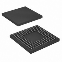
IC ARM MCU 16BIT 176BGA
Manufacturer
Atmel
Series
AT91SAMr
Specifications of AT91M55800A-33CJ
Core Processor
ARM7
Core Size
16/32-Bit
Speed
33MHz
Connectivity
EBI/EMI, SPI, UART/USART
Peripherals
POR, WDT
Number Of I /o
58
Program Memory Type
ROMless
Ram Size
8K x 8
Voltage - Supply (vcc/vdd)
2.7 V ~ 3.6 V
Data Converters
A/D 8x10b; D/A 2x10b
Oscillator Type
Internal
Operating Temperature
-40°C ~ 85°C
Package / Case
176-LFBGA
Processor Series
AT91Mx
Core
ARM7TDMI
Data Bus Width
32 bit
Data Ram Size
8 KB
Interface Type
EBI, SPI, USART
Maximum Clock Frequency
33 MHz
Number Of Programmable I/os
58
Number Of Timers
10 bit
Operating Supply Voltage
3 V to 3.6 V
Maximum Operating Temperature
+ 85 C
Mounting Style
SMD/SMT
3rd Party Development Tools
JTRACE-ARM-2M, MDK-ARM, RL-ARM, ULINK2
Development Tools By Supplier
AT91EB55
Minimum Operating Temperature
- 40 C
On-chip Adc
10 bit, 8 Channel
On-chip Dac
8 bit, 2 Channel
Cpu Family
AT91
Device Core
ARM7TDMI
Device Core Size
32b
Frequency (max)
33MHz
Program Memory Size
Not Required
Total Internal Ram Size
8KB
# I/os (max)
58
Number Of Timers - General Purpose
6
Operating Supply Voltage (typ)
3.3V
Operating Supply Voltage (max)
3.6V
Operating Supply Voltage (min)
2.7V
Instruction Set Architecture
RISC
Operating Temp Range
-40C to 85C
Operating Temperature Classification
Industrial
Mounting
Surface Mount
Pin Count
176
Package Type
BGA
For Use With
AT91EB55 - KIT EVAL FOR ARM AT91M55800A
Lead Free Status / RoHS Status
Contains lead / RoHS non-compliant
Eeprom Size
-
Program Memory Size
-
Lead Free Status / Rohs Status
Lead free / RoHS Compliant
Available stocks
Company
Part Number
Manufacturer
Quantity
Price
Company:

Part Number:
AT91M55800A-33CJ
Manufacturer:
ATMEL
Quantity:
590
Part Number:
AT91M55800A-33CJ
Manufacturer:
ATMEL/爱特梅尔
Quantity:
20 000
Company:
Part Number:
AT91M55800A-33CJ SL383
Manufacturer:
Atmel
Quantity:
10 000


12.3.3
12.3.4
1745F–ATARM–06-Sep-07
PLL Filter
Master Clock Selection
Note:
If the PLL multiplication is changed while the PLL is already active, the LOCK bit in APMC_SR is
automatically cleared and the same sequence is restarted. The PLL is automatically bypassed
while the frequency is changing (while LOCK is 0). If the Main Oscillator is reactivated at the
same time the PLL is enabled, the LOCK bit is set only when both the Main Oscillator and the
PLL are stabilized.
The Phase Lock Loop has a dedicated PLLRC pin which must connect with an appropriate sec-
ond order filter made up of one resistor and two capacitors. If the integrated PLL is not used, it
can remain disabled. The PLLRC pin must be grounded if the resistor and the capacitors need to
be saved. The following figure shows a typical filter connection.
Figure 12-5. Typical Filter Connection
In order to obtain optimal results with a 16 MHz input frequency and a 32 MHz output frequency,
the typical component values for the PLL filter are:
R = 287Ω - C1 = 680 nF - C2 = 68 nF
The lock time with these values is about 3.5 µs in this example.
The MCK (Master Clock) can be selected through the CSS field in APMC_CGMR between the
Slow Clock, the output of the Main Oscillator or the output of the PLL.
The following CSS field definitions are forbidden and the write operations are not taken into
account by the APMC:
This clock switch is performed in some Slow Clocks and PLLs or Main Oscillator clock cycles as
described in the state machine diagram below:
• deselect the Slow Clock if the Main Oscillator is disabled or its output is not stabilized
• disable the PLL without having first selected the Slow Clock or the Main Oscillator clock
• select the PLL clock and, in the same register, write disable the PLL
• select either the Main Oscillator or the PLL clocks and, in the same register, write disable the
• disable the Main Oscillator without having first selected the Slow Clock
Main Oscillator
Programming one in PLLCOUNT is the minimum allowed and guarantees at least 2 Slow Clock
cycles before the lock bit is set. Programming n in PLLCOUNT guarantees (n+1) the delay of Slow
Clock cycles. When the PLL Counter reaches 0, the LOCK bit in APMC_SR is set and can cause
an interrupt. Programming MUL or PLLCOUNT before the LOCK bit is set may lead to unpredict-
able behavior.
GNDPLL
PLLRC
C
R
1
C
2
AT91M5880A
57
Related parts for AT91M55800A-33CJ
Image
Part Number
Description
Manufacturer
Datasheet
Request
R

Part Number:
Description:
IC ARM7 MCU 176 TQFP
Manufacturer:
Atmel
Datasheet:

Part Number:
Description:
IC ARM7 MCU 176 BGA
Manufacturer:
Atmel
Datasheet:

Part Number:
Description:
DEV KIT FOR AVR/AVR32
Manufacturer:
Atmel
Datasheet:

Part Number:
Description:
INTERVAL AND WIPE/WASH WIPER CONTROL IC WITH DELAY
Manufacturer:
ATMEL Corporation
Datasheet:
Part Number:
Description:
Low-Voltage Voice-Switched IC for Hands-Free Operation
Manufacturer:
ATMEL Corporation
Datasheet:
Part Number:
Description:
MONOLITHIC INTEGRATED FEATUREPHONE CIRCUIT
Manufacturer:
ATMEL Corporation
Datasheet:
Part Number:
Description:
AM-FM Receiver IC U4255BM-M
Manufacturer:
ATMEL Corporation
Datasheet:
Part Number:
Description:
Monolithic Integrated Feature Phone Circuit
Manufacturer:
ATMEL Corporation
Datasheet:
Part Number:
Description:
Multistandard Video-IF and Quasi Parallel Sound Processing
Manufacturer:
ATMEL Corporation
Datasheet:
Part Number:
Description:
High-performance EE PLD
Manufacturer:
ATMEL Corporation
Datasheet:
Part Number:
Description:
8-bit Flash Microcontroller
Manufacturer:
ATMEL Corporation
Datasheet:
Part Number:
Description:
2-Wire Serial EEPROM
Manufacturer:
ATMEL Corporation
Datasheet: