AT32UC3L064-AUT Atmel, AT32UC3L064-AUT Datasheet - Page 613
AT32UC3L064-AUT
Manufacturer Part Number
AT32UC3L064-AUT
Description
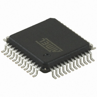
MCU AVR32 64KB FLASH 48TQFP
Manufacturer
Atmel
Series
AVR®32 UC3r
Datasheets
1.ATAVRONE-PROBECBL.pdf
(16 pages)
2.AT32UC3L-EK.pdf
(858 pages)
3.AT32UC3L016-D3HT.pdf
(110 pages)
Specifications of AT32UC3L064-AUT
Core Processor
AVR
Core Size
32-Bit
Speed
50MHz
Connectivity
I²C, SPI, UART/USART
Peripherals
Brown-out Detect/Reset, DMA, PWM, WDT
Number Of I /o
36
Program Memory Size
64KB (64K x 8)
Program Memory Type
FLASH
Ram Size
16K x 8
Voltage - Supply (vcc/vdd)
1.62 V ~ 3.6 V
Data Converters
A/D 9x10b
Oscillator Type
Internal
Operating Temperature
-40°C ~ 85°C
Package / Case
48-TQFP, 48-VQFP
Processor Series
AT32UC3x
Core
AVR32
Data Bus Width
32 bit
Data Ram Size
16 KB
Interface Type
SPI/TWI/USART
Maximum Clock Frequency
50 MHz
Number Of Programmable I/os
36
Number Of Timers
7
Maximum Operating Temperature
+ 85 C
Mounting Style
SMD/SMT
3rd Party Development Tools
EWAVR32, EWAVR32-BL
Development Tools By Supplier
AT32UC3L-EK
Minimum Operating Temperature
- 40 C
On-chip Adc
9-ch x 10-bit
Package
48TQFP
Device Core
AVR32
Family Name
AT32
Maximum Speed
50 MHz
Operating Supply Voltage
1.8|3.3 V
Lead Free Status / RoHS Status
Lead free / RoHS Compliant
Eeprom Size
-
Lead Free Status / Rohs Status
Lead free / RoHS Compliant
Available stocks
Company
Part Number
Manufacturer
Quantity
Price
Company:

Part Number:
AT32UC3L064-AUT
Manufacturer:
HONGFA
Quantity:
30 000
Part Number:
AT32UC3L064-AUT
Manufacturer:
MICROCHIP/微芯
Quantity:
20 000


26.8
26.8.1
26.8.2
26.8.3
32099F–11/2010
Operating Modes
Conversion Triggers
ADC Mode
Resistive Touch Screen Mode
The ADCIFB features two operating modes, each defining a separate conversion sequence:
The operating mode is selected by the TSAMOD field in the Mode Register (MR).
A conversion sequence is started either by a software or by a hardware trigger. When a conver-
sion sequence is started, all enabled channels will be converted and made available in the
shared Last Converted Register (LCDR).
The software trigger is asserted by writing a one to the START field in the Control Register (CR).
The hardware trigger can be selected by the TRGMOD field in the Trigger Register (TRGR). Dif-
ferent hardware triggers exist:
Enabling a hardware trigger does not disable the software trigger functionality. Thus, if a hard-
ware trigger is selected, the start of a conversion can still be initiated by the software trigger.
In the ADC Mode, the active channels are defined by the Channel Status Register (CHSR). A
channel is enabled by writing a one to the corresponding bit in the Channel Enable Register
(CHER), and disabled by writing a one to the corresponding bit in the Channel Disable Register
(CHDR). The conversion results are stored in the Last Converted Data Register (LCDR) as they
become available, overwriting old conversions.
At each trigger, the following sequence is performed:
If the Peripheral DMA Controller is enabled, all converted values are transferred continuously
into the memory buffer.
Writing a one to the TSAMOD field in the Mode Register (MR) enables Resistive Touch Screen
Mode. In this mode the channels TSPO+0 to TSPO+3, corresponding to the resistive touch
• ADC Mode: At each trigger, all the enabled channels are converted.
• Resistive Touch Screen Mode: At each trigger, all enabled channels plus the resistive touch
• External trigger, either rising or falling or any, detected on the external trigger pin TRIGGER
• Pen detect trigger, depending the PENDET bit in the Mode Register (MR)
• Continuous trigger, meaning the ADCIFB restarts the next sequence as soon as it finishes
• Periodic trigger, which is defined by the TRGR.TRGPER field
• Peripheral event trigger, allowing the Peripheral Event System to synchronize conversion with
1. If ACR.SLEEP is one, wake up the ADC and wait for the startup time.
2. If Channel 0 is enabled, convert Channel 0 and store result in LCDR.
3. If Channel 1 is enabled, convert Channel 1 and store result in LCDR.
4. If Channel N is enabled, convert Channel N and store result in LCDR.
5. If ACR.SLEEP is one, place the ADC cell in a low-power state.
screen channels are converted as described in
dedicated resistive touch screen channels are enabled, they are converted normally before
and after the resistive touch screen channels are converted.
the current one
some configured peripheral event source.
Section
AT32UC3L016/32/64
26.8.3. If channels except the
613
Related parts for AT32UC3L064-AUT
Image
Part Number
Description
Manufacturer
Datasheet
Request
R

Part Number:
Description:
KIT DEV/EVAL FOR AT32UC3L0
Manufacturer:
Atmel
Datasheet:
Part Number:
Description:
KIT EVAL AVR32 UC3 MCU
Manufacturer:
Atmel
Datasheet:

Part Number:
Description:
DEV KIT FOR AVR/AVR32
Manufacturer:
Atmel
Datasheet:

Part Number:
Description:
INTERVAL AND WIPE/WASH WIPER CONTROL IC WITH DELAY
Manufacturer:
ATMEL Corporation
Datasheet:
Part Number:
Description:
Low-Voltage Voice-Switched IC for Hands-Free Operation
Manufacturer:
ATMEL Corporation
Datasheet:
Part Number:
Description:
MONOLITHIC INTEGRATED FEATUREPHONE CIRCUIT
Manufacturer:
ATMEL Corporation
Datasheet:
Part Number:
Description:
AM-FM Receiver IC U4255BM-M
Manufacturer:
ATMEL Corporation
Datasheet:
Part Number:
Description:
Monolithic Integrated Feature Phone Circuit
Manufacturer:
ATMEL Corporation
Datasheet:
Part Number:
Description:
Multistandard Video-IF and Quasi Parallel Sound Processing
Manufacturer:
ATMEL Corporation
Datasheet:
Part Number:
Description:
High-performance EE PLD
Manufacturer:
ATMEL Corporation
Datasheet:
Part Number:
Description:
8-bit Flash Microcontroller
Manufacturer:
ATMEL Corporation
Datasheet:
Part Number:
Description:
2-Wire Serial EEPROM
Manufacturer:
ATMEL Corporation
Datasheet: