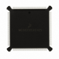
MC68332GVEH25 Freescale Semiconductor, MC68332GVEH25 Datasheet - Page 115

MC68332GVEH25
Manufacturer Part Number
MC68332GVEH25
Description
IC MCU 32BIT 25MHZ 132-PQFP
Manufacturer
Freescale Semiconductor
Series
M683xxr
Specifications of MC68332GVEH25
Core Processor
CPU32
Core Size
32-Bit
Speed
25MHz
Connectivity
EBI/EMI, SCI, SPI, UART/USART
Peripherals
POR, PWM, WDT
Number Of I /o
15
Program Memory Type
ROMless
Ram Size
2K x 8
Voltage - Supply (vcc/vdd)
4.5 V ~ 5.5 V
Oscillator Type
Internal
Operating Temperature
-40°C ~ 105°C
Package / Case
132-QFP
Processor Series
M683xx
Core
CPU32
Data Bus Width
32 bit
Controller Family/series
68K
No. Of I/o's
15
Ram Memory Size
2KB
Cpu Speed
25MHz
No. Of Timers
1
Embedded Interface Type
QSPI, SCI, UART
Digital Ic Case Style
PQFP
Rohs Compliant
Yes
Data Ram Size
2 KB
Interface Type
QSPI, SCI, UART
Maximum Clock Frequency
25 MHz
Number Of Programmable I/os
15
Number Of Timers
16
Maximum Operating Temperature
+ 105 C
Mounting Style
SMD/SMT
Minimum Operating Temperature
- 40 C
Lead Free Status / RoHS Status
Request inventory verification / Request inventory verification
Eeprom Size
-
Program Memory Size
-
Data Converters
-
Lead Free Status / Rohs Status
Lead free / RoHS Compliant
Available stocks
Company
Part Number
Manufacturer
Quantity
Price
Company:
Part Number:
MC68332GVEH25
Manufacturer:
Freescale Semiconductor
Quantity:
135
Company:
Part Number:
MC68332GVEH25
Manufacturer:
Freescale Semiconductor
Quantity:
10 000
- Current page: 115 of 265
- Download datasheet (7Mb)
5.10.2.1 Enabling BDM
5.10.2.2 BDM Sources
MC68332
USER’S MANUAL
Accidentally entering BDM in a non-development environment can lock up the CPU32
when the serial command interface is not available. For this reason, BDM is enabled
during reset via the breakpoint (BKPT) signal.
BDM operation is enabled when BKPT is asserted (low), at the rising edge of RESET.
BDM remains enabled until the next system reset. A high BKPT signal on the trailing
edge of RESET disables BDM. BKPT is latched again on each rising transition of RE-
SET. BKPT is synchronized internally, and must be held low for at least two clock cy-
cles prior to negation of RESET.
BDM enable logic must be designed with special care. If hold time on BKPT extends
into the first bus cycle following reset, the bus cycle could inadvertently be tagged with
a breakpoint. Refer to the SIM Reference Manual (SIMRM/AD) for timing information.
When BDM is enabled, any of several sources can cause the transition from normal
mode to BDM. These sources include external breakpoint hardware, the BGND in-
struction, a double bus fault, and internal peripheral breakpoints. If BDM is not enabled
when an exception condition occurs, the exception is processed normally. Table 5-3
summarizes the processing of each source for both enabled and disabled cases. As
shown in Table 5-3, the BKPT instruction never causes a transition into BDM.
TARGET
SYSTEM
BGND Instruction
Double Bus Fault
BKPT Instruction
Figure 5-8 Bus State Analyzer Configuration
Source
BKPT
Freescale Semiconductor, Inc.
For More Information On This Product,
Table 5-3 BDM Source Summary
CENTRAL PROCESSING UNIT
TARGET
Go to: www.freescale.com
MCU
Opcode Substitution/
Illegal Instruction
BUS STATE
ANALYZER
BDM Enabled
Background
Background
Background
Breakpoint Exception
Opcode Substitution/
Illegal Instruction
Illegal Instruction
BDM Disabled
Halted
1129A
5-17
Related parts for MC68332GVEH25
Image
Part Number
Description
Manufacturer
Datasheet
Request
R
Part Number:
Description:
Manufacturer:
Freescale Semiconductor, Inc
Datasheet:
Part Number:
Description:
Manufacturer:
Freescale Semiconductor, Inc
Datasheet:
Part Number:
Description:
Manufacturer:
Freescale Semiconductor, Inc
Datasheet:
Part Number:
Description:
Manufacturer:
Freescale Semiconductor, Inc
Datasheet:
Part Number:
Description:
Manufacturer:
Freescale Semiconductor, Inc
Datasheet:
Part Number:
Description:
Manufacturer:
Freescale Semiconductor, Inc
Datasheet:
Part Number:
Description:
Manufacturer:
Freescale Semiconductor, Inc
Datasheet:
Part Number:
Description:
Manufacturer:
Freescale Semiconductor, Inc
Datasheet:
Part Number:
Description:
Manufacturer:
Freescale Semiconductor, Inc
Datasheet:
Part Number:
Description:
Manufacturer:
Freescale Semiconductor, Inc
Datasheet:
Part Number:
Description:
Manufacturer:
Freescale Semiconductor, Inc
Datasheet:
Part Number:
Description:
Manufacturer:
Freescale Semiconductor, Inc
Datasheet:
Part Number:
Description:
Manufacturer:
Freescale Semiconductor, Inc
Datasheet:
Part Number:
Description:
Manufacturer:
Freescale Semiconductor, Inc
Datasheet:
Part Number:
Description:
Manufacturer:
Freescale Semiconductor, Inc
Datasheet:


