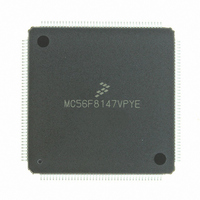
MC56F8147VPYE Freescale Semiconductor, MC56F8147VPYE Datasheet - Page 155

MC56F8147VPYE
Manufacturer Part Number
MC56F8147VPYE
Description
IC DSP 16BIT 40MHZ 160-LQFP
Manufacturer
Freescale Semiconductor
Series
56F8xxxr
Datasheet
1.MC56F8147VPYE.pdf
(172 pages)
Specifications of MC56F8147VPYE
Core Processor
56800
Core Size
16-Bit
Speed
40MHz
Connectivity
EBI/EMI, SCI, SPI
Peripherals
POR, PWM, WDT
Number Of I /o
76
Program Memory Size
128KB (64K x 16)
Program Memory Type
FLASH
Ram Size
4K x 16
Voltage - Supply (vcc/vdd)
2.25 V ~ 3.6 V
Data Converters
A/D 16x12b
Oscillator Type
External
Operating Temperature
-40°C ~ 105°C
Package / Case
160-LQFP
Data Bus Width
16 bit
Processor Series
MC56F81xx
Core
56800E
Data Ram Size
4 KB
Interface Type
SPI, SCI, CAN
Maximum Clock Frequency
40 MHz
Number Of Programmable I/os
76
Number Of Timers
2
Maximum Operating Temperature
+ 105 C
Mounting Style
SMD/SMT
Minimum Operating Temperature
- 40 C
On-chip Adc
4 x 12 bit, 4 Channel
Lead Free Status / RoHS Status
Lead free / RoHS Compliant
Eeprom Size
-
Lead Free Status / Rohs Status
Lead free / RoHS Compliant
Available stocks
Company
Part Number
Manufacturer
Quantity
Price
Company:
Part Number:
MC56F8147VPYE
Manufacturer:
FREESCAL
Quantity:
253
Company:
Part Number:
MC56F8147VPYE
Manufacturer:
Freescale Semiconductor
Quantity:
10 000
C, the internal [dynamic component], is classic C*V
56800E core and standard cell logic.
D, the external [dynamic component], reflects power dissipated on-chip as a result of capacitive loading
on the external pins of the chip. This is also commonly described as C*V
of the IO cell types used on the device reveal that the power-versus-load curve does have a non-zero
Y-intercept.
Power due to capacitive loading on output pins is (first order) a function of the capacitive load and
frequency at which the outputs change.
in the IO cells as a function of capacitive load. In these cases:
TotalPower = Σ((Intercept +Slope*Cload)*frequency/10MHz)
where:
Because of the low duty cycle on most device pins, power dissipation due to capacitive loads was found
to be fairly low when averaged over a period of time. The one possible exception to this is if the chip is
using the external address and data buses at a rate approaching the maximum system rate. In this case,
power from these buses can be significant.
E, the external [static component], reflects the effects of placing resistive loads on the outputs of the
device. Sum the total of all V
0.5 for the purposes of these rough calculations. For instance, if there is a total of 8 PWM outputs driving
10mA into LEDs, then P = 8*.5*.01 = 40mW.
In previous discussions, power consumption due to parasitics associated with pure input pins is ignored,
as it is assumed to be negligible.
Freescale Semiconductor
Preliminary
•
•
•
Summation is performed over all output pins with capacitive loads
TotalPower is expressed in mW
Cload is expressed in pF
Table 10-25 I/O Loading Coefficients at 10MHz
PDU08DGZ_ME
PDU04DGZ_ME
2
/R or IV to arrive at the resistive load contribution to power. Assume V =
56F8347 Technical Data, Rev.11
Table 10-25
provides coefficients for calculating power dissipated
2
Intercept
1.15mW
*F CMOS power dissipation corresponding to the
1.3
0.11mW / pF
0.11mW / pF
Slope
2
*F, although simulations on two
Power Consumption
155


