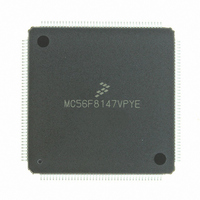
MC56F8147VPYE Freescale Semiconductor, MC56F8147VPYE Datasheet - Page 123

MC56F8147VPYE
Manufacturer Part Number
MC56F8147VPYE
Description
IC DSP 16BIT 40MHZ 160-LQFP
Manufacturer
Freescale Semiconductor
Series
56F8xxxr
Datasheet
1.MC56F8147VPYE.pdf
(172 pages)
Specifications of MC56F8147VPYE
Core Processor
56800
Core Size
16-Bit
Speed
40MHz
Connectivity
EBI/EMI, SCI, SPI
Peripherals
POR, PWM, WDT
Number Of I /o
76
Program Memory Size
128KB (64K x 16)
Program Memory Type
FLASH
Ram Size
4K x 16
Voltage - Supply (vcc/vdd)
2.25 V ~ 3.6 V
Data Converters
A/D 16x12b
Oscillator Type
External
Operating Temperature
-40°C ~ 105°C
Package / Case
160-LQFP
Data Bus Width
16 bit
Processor Series
MC56F81xx
Core
56800E
Data Ram Size
4 KB
Interface Type
SPI, SCI, CAN
Maximum Clock Frequency
40 MHz
Number Of Programmable I/os
76
Number Of Timers
2
Maximum Operating Temperature
+ 105 C
Mounting Style
SMD/SMT
Minimum Operating Temperature
- 40 C
On-chip Adc
4 x 12 bit, 4 Channel
Lead Free Status / RoHS Status
Lead free / RoHS Compliant
Eeprom Size
-
Lead Free Status / Rohs Status
Lead free / RoHS Compliant
Available stocks
Company
Part Number
Manufacturer
Quantity
Price
Company:
Part Number:
MC56F8147VPYE
Manufacturer:
FREESCAL
Quantity:
253
Company:
Part Number:
MC56F8147VPYE
Manufacturer:
Freescale Semiconductor
Quantity:
10 000
7.2.4
The recommended method of unsecuring a programmed device for product analysis of field failures is via
the backdoor key access. The customer would need to supply Technical Support with the backdoor key
and the protocol to access the backdoor routine in the Flash. Additionally, the KEYEN bit that allows
backdoor key access must be set.
An alternative method for performing analysis on a secured microcontroller would be to mass-erase and
reprogram the Flash with the original code, but modify the security bytes.
To insure that a customer does not inadvertently lock himself out of the device during programming, it is
recommended that he program the backdoor access key first, his application code second, and the security
bytes within the FM configuration field last.
Part 8 General Purpose Input/Output (GPIO)
8.1 Introduction
This section is intended to supplement the GPIO information found in the 56F8300 Peripheral User
Manual and contains only chip-specific information. This information supercedes the generic information
in the 56F8300 Peripheral User Manual.
8.2 Memory Maps
The width of the GPIO port defines how many bits are implemented in each of the GPIO registers. Based
on this and the default function of each of the GPIO pins, the reset values of the GPIOx_PUR and
GPIOx_PER registers change from port to port. Tables
these registers.
8.3 Configuration
There are six GPIO ports defined on the 56F8347/56F8147. The width of each port and the associated
peripheral function is shown in
shown in
Freescale Semiconductor
Preliminary
GPIO
Port
C
A
B
Table
Product Analysis
Width
Port
14
11
8
8-3.
Available
56F8347
Pins in
14
11
8
Table 8-1 56F8347 GPIO Ports Configuration
14 pins - EMI Address pins
8 pins - EMI Address pins
4 pins -DEC1 / TMRB / SPI1
4 pins -DEC0 / TMRA
3 pins -PWMA current sense
Table 8-1
56F8347 Technical Data, Rev.11
and
Peripheral Function
Table
4-29
8-2. The specific mapping of GPIO port pins is
through
4-34
define the actual reset values of
EMI Address
EMI Address
DEC1 / TMRB
DEC0 / TMRA
PWMA current sense
Reset Function
Introduction
123


