HW-V5-ML555-G Xilinx Inc, HW-V5-ML555-G Datasheet - Page 75
HW-V5-ML555-G
Manufacturer Part Number
HW-V5-ML555-G
Description
BOARD EVAL FOR VIRTEX-5 ML555
Manufacturer
Xilinx Inc
Series
Virtex™ -5r
Type
FPGAr
Datasheet
1.HW-V5-PCIE2-UNI-G.pdf
(108 pages)
Specifications of HW-V5-ML555-G
Contents
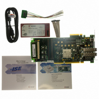
Board, Cables, CD
Silicon Manufacturer
Xilinx
Features
Parallel Connectivity, Three On-board Clock Sources
Kit Contents
Board, Cables, CD, Power Supply
Silicon Family Name
Virtex-5
Silicon Core Number
XC5VLX50T-1FF1136
Rohs Compliant
Yes
Lead Free Status / RoHS Status
Lead free / RoHS Compliant
For Use With/related Products
Virtex™-5 FPGA
For Use With
HW-AFX-SMA-SFP - CONVERSION MODULE SMA - SFPHW-AFX-SMA-SATA - CONVERSION MODULE SMA - SATAHW-AFX-SMA-RJ45 - CONVERSION MODULE SMA - RJ45HW-AFX-SMA-HSSDC2 - CONVERSION MODULE SMA - HSSDC2HW-AFX-BERG-EPHY - DAUGHTER CARD PHY BERG-EPHY
Lead Free Status / RoHS Status
Lead free / RoHS Compliant, Lead free / RoHS Compliant
Other names
122-1586
HW-V5-ML555-G
HW-V5-ML555-G
Available stocks
Company
Part Number
Manufacturer
Quantity
Price


Voltage Regulators
Virtex-5 FPGA ML555 Development Kit
UG201 (v1.4) March 10, 2008
ML555 DC Power System
R
The ML555 board is powered from either the PCI slot that it is plugged into, utilizing the
+5V and the +3.3V power rails (see
edge connector pinout), or the PCI Express slot that it is plugged into utilizing the +3.3V
and +12V power rails.
The ML555 board plugs into either a parallel PCI bus slot or a serial PCI Express slot in a
system unit. PCI and PCI Express designs use different connector systems for add-in cards.
System units provide unique DC voltages to the add-in cards through the connectors. PCI
system units provide 3.3V and 5V, while PCI Express system units provide 3.3V and 12V to
add-in cards. For PCI Express applications, the ML555 board converts the 12V supply to
5V before powering the onboard voltage regulators. For PCI applications, most of the
onboard regulators are powered by 5V provided by the system units.
The GTP transceiver analog supplies and the FPGA V
either 3.3V from the PCI Express connector or a 5V to 3.0V DC converter on the ML555
board. Two configuration headers are provided on the ML555 board to select between the
5V and 3.3V power sources as indicated in
diagram of the ML555 voltage regulator topology.
www.xilinx.com
Table 3-4
Table 3-30
for the specific power pins within the PCI
and
CCINT
Table
voltage are sourced from
3-31.
Figure 3-14
Voltage Regulators
is a block
75
Related parts for HW-V5-ML555-G
Image
Part Number
Description
Manufacturer
Datasheet
Request
R

Part Number:
Description:
EVAL PLATFORM V5 FXT
Manufacturer:
Xilinx Inc
Datasheet:

Part Number:
Description:
BOARD EVAL FOR VIRTEX-5
Manufacturer:
Xilinx Inc
Datasheet:
Part Number:
Description:
BOARD EVAL FOR VIRTEX-5
Manufacturer:
Xilinx Inc
Datasheet:

Part Number:
Description:
EVALUATION PLATFORM VIRTEX-5
Manufacturer:
Xilinx Inc
Datasheet:

Part Number:
Description:
EVALUATION PLATFORM VIRTEX-5
Manufacturer:
Xilinx Inc
Datasheet:
Part Number:
Description:
KIT DEV PCIEXPRESS GTX VIRTEX5
Manufacturer:
Xilinx Inc
Datasheet:

Part Number:
Description:
EVALUATION PLATFORM VIRTEX-5
Manufacturer:
Xilinx Inc
Datasheet:
Part Number:
Description:
BOARD EVAL FOR VIRTEX-5 ML510
Manufacturer:
Xilinx Inc
Datasheet:
Part Number:
Description:
EVALUATION PLATFORM VIRTEX-5
Manufacturer:
Xilinx Inc
Datasheet:
Part Number:
Description:
CoolRunner-II CPLD
Manufacturer:
XILINX [Xilinx, Inc]
Datasheet:
Part Number:
Description:
In-System Programmable CPLD
Manufacturer:
XILINX [Xilinx, Inc]
Datasheet:
Part Number:
Description:
High-Performance CPLD
Manufacturer:
XILINX [Xilinx, Inc]
Datasheet:
Part Number:
Description:
XCR3128XL 128 Macrocell CPLD
Manufacturer:
XILINX [Xilinx, Inc]
Datasheet:
Part Number:
Description:
XC95288XL High Performance CPLD
Manufacturer:
XILINX [Xilinx, Inc]
Datasheet: