HW-V5-ML555-G Xilinx Inc, HW-V5-ML555-G Datasheet - Page 39
HW-V5-ML555-G
Manufacturer Part Number
HW-V5-ML555-G
Description
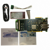
BOARD EVAL FOR VIRTEX-5 ML555
Manufacturer
Xilinx Inc
Series
Virtex™ -5r
Type
FPGAr
Datasheet
1.HW-V5-PCIE2-UNI-G.pdf
(108 pages)
Specifications of HW-V5-ML555-G
Contents
Board, Cables, CD
Silicon Manufacturer
Xilinx
Features
Parallel Connectivity, Three On-board Clock Sources
Kit Contents
Board, Cables, CD, Power Supply
Silicon Family Name
Virtex-5
Silicon Core Number
XC5VLX50T-1FF1136
Rohs Compliant
Yes
Lead Free Status / RoHS Status
Lead free / RoHS Compliant
For Use With/related Products
Virtex™-5 FPGA
For Use With
HW-AFX-SMA-SFP - CONVERSION MODULE SMA - SFPHW-AFX-SMA-SATA - CONVERSION MODULE SMA - SATAHW-AFX-SMA-RJ45 - CONVERSION MODULE SMA - RJ45HW-AFX-SMA-HSSDC2 - CONVERSION MODULE SMA - HSSDC2HW-AFX-BERG-EPHY - DAUGHTER CARD PHY BERG-EPHY
Lead Free Status / RoHS Status
Lead free / RoHS Compliant, Lead free / RoHS Compliant
Other names
122-1586
HW-V5-ML555-G
HW-V5-ML555-G
Available stocks
Company
Part Number
Manufacturer
Quantity
Price


Small Form-factor Pluggable (SFP) Module Interface
Table 3-7: SFP Connectors
Virtex-5 FPGA ML555 Development Kit
UG201 (v1.4) March 10, 2008
Notes:
1. Transceiver port names do not include the “{1/2}” shown in this table. Replace “{1/2}” with “SFP1” or “SFP2” as the prefix or suffix
2. The I
3. NC = no connect.
4. TX_FAULT input from SFP goes to a board testpoint only.
5. TX_DISABLE has an on-board 4.7 KΩ pull-down resistor. By default, the transceiver is enabled. Some SFP modules require a
6. TCVR_PRESENT is not connected to the FPGA.
7. RATE_SEL is pulled up to 3.3V with a 4.7 KΩ resistor. P26 or P29 (pin 1 or 2) is shorted to ground to select a different transmission
8. Loss of signal from the SFP interface is connected to light emitting diode (LED) D7 for SFP1 and D8 for SFP2.
in the port name. The SFP ports are connected to GTP_DUAL tile X0Y4.
stronger pull-down resistor to enable the transmitter. In this situation, resistors R394 and R402 on the ML555 board should be
replaced with a 1 KΩ or lower value resistor to force the transmitter to be enabled.
rate.
SFP1-J3
2
C interface signals are connected to FPGA bank 20. The reference voltage, V
10
11
12
13
14
15
16
17
18
19
20
1
2
3
4
5
6
7
8
9
R
SFP{1/2}_TCVR_PRESENT_B
The ML555 board has two SFP connectors that support user-installed SFP modules to
support Fibre Channel and Gigabit Ethernet interfaces. The interface is compliant with the
multi-source agreement specification entitled Cooperation Agreement for Small Form-
Factor Pluggable Transceivers.
connectivity. The ML555 board provides filtered 3.3V power to both SFP modules per the
SFP specification.
The ML555 kit does not include SFP modules to plug into the connectors. The user must
provide these.
SFP{1/2}_TX_DISABLE
SFP{1/2}_TX_FAULT
SFP{1/2}_RATE_SEL
IIC_SDA_SFP{1/2}
II2_SCK_SFP{1/2}
SFP{1/2}_LOS
SFP{1/2}_RXN
SFP{1/2}_TXN
SFP{1/2}_RXP
SFP{1/2}_TXP
SFP_RX_3.3V
SFP_TX_3.3V
Signal
GND
GND
GND
GND
GND
GND
GND
(1)
(8)
(7)
(4)
(5)
www.xilinx.com
(6)
Table 3-7
Small Form-factor Pluggable (SFP) Module Interface
FPGA Pin
NC
NC
NC
NC
NC
NC
NC
NC
NC
NC
NC
NC
NC
NC
H1
G1
G2
E8
E9
F2
lists the connector pins and any associated FPGA
(3)
(2)
CCO
, for this bank is 2.5V.
SFP2-J4
10
12
13
14
15
16
17
18
19
20
11
1
2
3
4
5
6
7
8
9
FPGA Pin
NC
NC
NC
NC
NC
NC
NC
NC
NC
NC
NC
NC
NC
NC
K1
L2
K2
F8
F9
J1
39
Related parts for HW-V5-ML555-G
Image
Part Number
Description
Manufacturer
Datasheet
Request
R

Part Number:
Description:
EVAL PLATFORM V5 FXT
Manufacturer:
Xilinx Inc
Datasheet:

Part Number:
Description:
BOARD EVAL FOR VIRTEX-5
Manufacturer:
Xilinx Inc
Datasheet:
Part Number:
Description:
BOARD EVAL FOR VIRTEX-5
Manufacturer:
Xilinx Inc
Datasheet:

Part Number:
Description:
EVALUATION PLATFORM VIRTEX-5
Manufacturer:
Xilinx Inc
Datasheet:

Part Number:
Description:
EVALUATION PLATFORM VIRTEX-5
Manufacturer:
Xilinx Inc
Datasheet:
Part Number:
Description:
KIT DEV PCIEXPRESS GTX VIRTEX5
Manufacturer:
Xilinx Inc
Datasheet:

Part Number:
Description:
EVALUATION PLATFORM VIRTEX-5
Manufacturer:
Xilinx Inc
Datasheet:
Part Number:
Description:
BOARD EVAL FOR VIRTEX-5 ML510
Manufacturer:
Xilinx Inc
Datasheet:
Part Number:
Description:
EVALUATION PLATFORM VIRTEX-5
Manufacturer:
Xilinx Inc
Datasheet:
Part Number:
Description:
CoolRunner-II CPLD
Manufacturer:
XILINX [Xilinx, Inc]
Datasheet:
Part Number:
Description:
In-System Programmable CPLD
Manufacturer:
XILINX [Xilinx, Inc]
Datasheet:
Part Number:
Description:
High-Performance CPLD
Manufacturer:
XILINX [Xilinx, Inc]
Datasheet:
Part Number:
Description:
XCR3128XL 128 Macrocell CPLD
Manufacturer:
XILINX [Xilinx, Inc]
Datasheet:
Part Number:
Description:
XC95288XL High Performance CPLD
Manufacturer:
XILINX [Xilinx, Inc]
Datasheet: