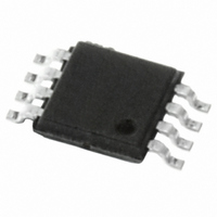
M34E02-FDW1TP STMicroelectronics, M34E02-FDW1TP Datasheet - Page 33

M34E02-FDW1TP
Manufacturer Part Number
M34E02-FDW1TP
Description
IC EEPROM 2KBIT 400KHZ 8TSSOP
Manufacturer
STMicroelectronics
Datasheet
1.M34E02-FMB1TG.pdf
(34 pages)
Specifications of M34E02-FDW1TP
Format - Memory
EEPROMs - Serial
Memory Type
EEPROM
Memory Size
2K (256 x 8)
Speed
400kHz
Interface
I²C, 2-Wire Serial
Voltage - Supply
1.7 V ~ 3.6 V
Operating Temperature
0°C ~ 70°C
Package / Case
8-TSSOP
Organization
256 K x 8
Interface Type
2-Wire
Maximum Clock Frequency
0.4 MHz
Access Time
900 ns
Supply Voltage (max)
3.6 V
Supply Voltage (min)
1.7 V
Maximum Operating Current
2 mA
Maximum Operating Temperature
+ 70 C
Mounting Style
SMD/SMT
Minimum Operating Temperature
0 C
Operating Supply Voltage
1.7 V, 3.6 V
Lead Free Status / RoHS Status
Lead free / RoHS Compliant
Other names
497-8654-2
M34E02-FDW1TP
M34E02-FDW1TP
Available stocks
Company
Part Number
Manufacturer
Quantity
Price
Company:
Part Number:
M34E02-FDW1TP
Manufacturer:
NS
Quantity:
500
Part Number:
M34E02-FDW1TP
Manufacturer:
ST
Quantity:
20 000
M34E02
Table 18.
18-Mar-2009
25-Sep-2009
01-Apr-2010
Date
Document revision history (continued)
Revision
7
8
9
Datasheet title and
with DDR1 and DDR2 DRAM configurations.
Temperature range 6 added, operating voltage range V
device temperature range 6. I
Absolute maximum
I
range 6
characteristics (for temperature range 6 devices)
waveforms
Figure 4: Maximum RP value versus bus parasitic capacitance (C) for an
I2C bus
block
UFDFPN8 package specifications updated (see
(MLP8) 8-lead ultra thin fine pitch dual flat package no lead 2 x 3 mm,
data).
Blank option removed under plating technology in
information
Section 2.5.2: Power-up conditions
updated.
(C) for an I2C bus
t
I
temperature range 1
Test condition updated in
Updated
package no lead 2 x 3 mm, outline
LO
NS
CC
, I
modified in
and V
CC
diagram.
Doc ID 10367 Rev 9
and V
devices).
updated. Note removed below
Figure 14: UFDFPN8 (MLP8) 8-lead ultra thin fine pitch dual flat
Figure 4: Maximum RP value versus bus parasitic capacitance
IL
modified.
scheme. Small text changes.
test conditions extended in
IL
Table 11: Input
modified in
Table 14: AC characteristics
modified.
Features on page 1
ratings.
devices).
Table 12 on page 24
Table 13: DC characteristics (for temperature
OL
parameters.
Changes
added to and T
and
and
Figure 11: Serial presence detect
Table 12: DC characteristics (for
Table 15 on page 29
modified: the device can be used
Section 2.5.3: Device reset
added.
and
A
Table 15: UFDFPN8
modified.
modified in
Table 17: Ordering
Table 13 on page 25
Table 13: DC
Revision history
CC
extended in
Figure 13: AC
Table 7:
33/34


