TDGL003 Microchip Technology, TDGL003 Datasheet - Page 101
TDGL003
Manufacturer Part Number
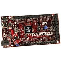
TDGL003
Description
ChipKIT Max32 Development Board PIC32 Boards And Kits
Manufacturer
Microchip Technology
Series
PIC® 32MXr
Type
MCUr
Specifications of TDGL003
Silicon Manufacturer
Microchip
Core Architecture
MIPS
Core Sub-architecture
PIC32
Silicon Core Number
PIC32MX
Silicon Family Name
PIC32MX795Fxxxx
Kit Contents
Board Only
Contents
Board
Lead Free Status / Rohs Status
Lead free / RoHS Compliant
For Use With/related Products
MPLAB®, Arduino™ Mega


12.0
FIGURE 12-1:
© 2011 Microchip Technology Inc.
Note 1: This data sheet summarizes the features
Legend:
Note:
2: Some registers and associated bits
I/O PORTS
PIO Module
of the PIC32MX3XX/4XX family of
devices. It is not intended to be a
comprehensive reference source. To
complement the information in this data
sheet, refer to Section 12. “I/O Ports”
(DS61120)
Reference Manual”, which is available
from
(www.microchip.com/PIC32).
described in this section may not be
available on all devices. Refer to
Section 4.0 “Memory Organization”
this data sheet for device-specific register
and bit information.
WR PORT
R = Peripheral input buffer types may vary. Refer to
This block diagram is a general representation of a shared port/peripheral structure for illustration purposes only. The actual structure
for any specific port/peripheral combination may be different than it is shown here.
WR TRIS
RD PORT
WR ODC
Peripheral Input
Data Bus
RD ODC
RD TRIS
SYS
WR LAT
SYS
RD LAT
Sleep
CLK
CLK
the
BLOCK DIAGRAM OF A TYPICAL MULTIPLEXED PORT STRUCTURE
of
Microchip
Peripheral Input Buffer
the
Peripheral Module Enable
Peripheral Output Enable
Peripheral Output Data
Peripheral Module
“PIC32
web
D
D
D
CK
CK
CK
Family
EN Q
EN Q
EN Q
R
site
Q
Q
Q
in
Table 1-1
ODC
TRIS
LAT
1
0
Q
for peripheral details.
Output Multiplexers
Q
General purpose I/O pins are the simplest of peripher-
als. They allow the PIC
other devices. To add flexibility and functionality, some
pins are multiplexed with alternate function(s). These
functions depend on which peripheral features are on
the device. In general, when a peripheral is functioning,
that pin may not be used as a general purpose I/O pin.
Following are some of the key features of this module:
• Individual Output Pin Open-drain Enable/Disable
• Individual Input Pin Weak Pull-up Enable/Disable
• Monitor Selective Inputs and Generate Interrupt
• Operation during CPU Sleep and Idle modes
• Fast Bit Manipulation using CLR, SET and INV
Figure 12-1
multiplexed I/O port.
Synchronization
CK
when Change in Pin State is Detected
Registers
D
1
0
1
0
PIC32MX3XX/4XX
Q
Q
illustrates a block diagram of a typical
CK
D
0
1
®
MCU to monitor and control
I/O Cell
DS61143H-page 101
I/O Pin
Related parts for TDGL003
Image
Part Number
Description
Manufacturer
Datasheet
Request
R

Part Number:
Description:
Manufacturer:
Microchip Technology Inc.
Datasheet:
Part Number:
Description:
Manufacturer:
Microchip Technology Inc.
Datasheet:
Part Number:
Description:
Manufacturer:
Microchip Technology Inc.
Datasheet:
Part Number:
Description:
Manufacturer:
Microchip Technology Inc.
Datasheet:
Part Number:
Description:
Manufacturer:
Microchip Technology Inc.
Datasheet:
Part Number:
Description:
Manufacturer:
Microchip Technology Inc.
Datasheet:
Part Number:
Description:
Manufacturer:
Microchip Technology Inc.
Datasheet:
Part Number:
Description:
Manufacturer:
Microchip Technology Inc.
Datasheet: