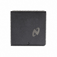
DP8344BV National Semiconductor, DP8344BV Datasheet - Page 178

DP8344BV
Manufacturer Part Number
DP8344BV
Description
IC BIPHASE COMM PROCESSR 84-PLCC
Manufacturer
National Semiconductor
Datasheet
1.DP8344BV.pdf
(184 pages)
Specifications of DP8344BV
Processor Type
8-Bit RISC
Speed
20MHz
Voltage
4.5 ~ 5.5V
Mounting Type
Surface Mount
Package / Case
84-PLCC
Operating Supply Voltage (typ)
5V
Operating Supply Voltage (max)
5.5V
Operating Supply Voltage (min)
4.5V
Mounting
Surface Mount
Operating Temperature (max)
70C
Operating Temperature (min)
0C
Operating Temperature Classification
Commercial
Lead Free Status / RoHS Status
Contains lead / RoHS non-compliant
Features
-
Lead Free Status / Rohs Status
Not Compliant
Other names
*DP8344BV
Available stocks
Company
Part Number
Manufacturer
Quantity
Price
Company:
Part Number:
DP8344BV
Manufacturer:
NSC
Quantity:
5 510
Part Number:
DP8344BV
Manufacturer:
NS/国半
Quantity:
20 000
Receiver
Error Codes
6 0 Reference Section
6 2 3 Bit Definition Tables (Continued)
6 2 3 2 Transceiver (Continued)
Table includes control and status bits only It does not include definitions of bit fields provided for the formatting (de-formatting)
data frames For further information see the Transceiver section
6 3 REMOTE INTERFACE CONFIGURATION REGISTER
This register can be accessed only by the remote system
To do this CMD and RAE must be asserted and the LOR
bit in the ACR register must be low
BIS
SS
FW
LR
LW
STRT
BIS SS FW LR LW STRT MS1 MS0 RIC
7
Bidirectional Interrupt Status
of IM3 ( ICR bit 3) enabling the remote system to
poll and determine the status of the BIRQ I O
When BIRQ is an output the remote system can
change the state of this output by writing a one to
BIS This can be used as an interrupt acknowl-
edge whenever BIRQ is used as a remote inter-
rupt For complete information on the relationship
between BIS IM3 and BIRQ refer to Section 2 2 3
Interrupts
Single-Step
will single-step by executing the current instruction
and advancing the PC On power up reset this bit
is low
Fast Write
write mode for the buffered interface When low
selects slow write mode On power up reset this
bit is low (LW will also be low so buffered write
mode is selected)
Latched Read
mode when low selects buffered read mode On
power up reset this bit is low (Buffered read mode
is selected )
Latched Write
mode when low selects buffered write mode On
power up reset this bit is low (FW will also be low
so slow buffered write mode is selected)
STaRT
the BCP using this bit On power-up reset this bit is
6
IES
LMBT
OVF
PAR
RDIS
Bit
5
The remote system can start and stop
4
Invalid Ending
Sequence
Loss of Mid-Bit
Transition
receiver OVerFlow ECR 4
PARity error
Receiver DISabled ECR 0
while active
When high with LW low selects fast
Writing a 1 with STRT low the BCP
3
When high selects latched write
When high selects latched read
Name
2
(Continued)
1
Location Reset State
ECR 2
ECR 1
ECR 3
Mirrors the state
0
0
0
0
0
0
178
MS1 0
Set when the first mini-code violation is not correct during a
3270 3299 or 8-bit ending sequence Cleared by reading
Set when the expected Manchester Code mid-bit transition
does not occur within the allowed window Cleared by reading
Set when the receiver has processed 3 words and another
complete frame is received before the FIFO is read by the
CPU Cleared by reading ECR or asserting TRES
Set when bad (odd) overall word parity is detected in any
receive frame Cleared by reading ECR or asserting
Set when transmitter is activated by writing to RTR while
receiver is still active without RPEN first being asserted
Cleared by reading ECR or asserting TRES
TRES
ECR or asserting TRES
ECR or by asserting TRES
low (BCP stopped) When set the BCP begins exe-
cuting at the current Program Counter address
When cleared the BCP finishes executing the cur-
rent instruction then halts to an idle mode
In some applications where there is no remote
system or the remote system is not an intelligent
device it may be desirable to have the BCP power-
up reset running rather than stopped at address
0000H This can be accomplished by asserting
REM-RD REM-WR and RESET with RAE de-as-
serted (Refer to Electrical Specification Section
for the timing information needed to start the BCP
in stand alone mode )
Memory Select 1 0
what the remote system is accessing in the BCP
system according to the following table
The BCP must be idle for the remote system to
read write Instruction memory or the Program
Counter
All remote accesses are treated the same (inde-
pendent of where the access is directed using MS0
and MS1) as defined by the configuration bits LW
LR FW
If the remote system and the BCP request data
memory access simultaneously the BCP will win
first access If the locks ( LOR LOCK) are not set
the remote system and BCP will alternate access
cycles thereafter
On power-up reset MS1 0 points to instruction
memory
Power-up Reset state of RIC 7-0
MS1
0
0
1
1
MS0
0
1
0
1
Function
Data Memory
Instruction Memory
Program Counter (Low Byte)
Program Counter (High Byte)
Selected Function
These two bits determine
is
l
000 000
l


