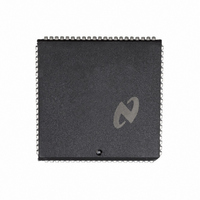
DP8344BV National Semiconductor, DP8344BV Datasheet - Page 139

DP8344BV
Manufacturer Part Number
DP8344BV
Description
IC BIPHASE COMM PROCESSR 84-PLCC
Manufacturer
National Semiconductor
Datasheet
1.DP8344BV.pdf
(184 pages)
Specifications of DP8344BV
Processor Type
8-Bit RISC
Speed
20MHz
Voltage
4.5 ~ 5.5V
Mounting Type
Surface Mount
Package / Case
84-PLCC
Operating Supply Voltage (typ)
5V
Operating Supply Voltage (max)
5.5V
Operating Supply Voltage (min)
4.5V
Mounting
Surface Mount
Operating Temperature (max)
70C
Operating Temperature (min)
0C
Operating Temperature Classification
Commercial
Lead Free Status / RoHS Status
Contains lead / RoHS non-compliant
Features
-
Lead Free Status / Rohs Status
Not Compliant
Other names
*DP8344BV
Available stocks
Company
Part Number
Manufacturer
Quantity
Price
Company:
Part Number:
DP8344BV
Manufacturer:
NSC
Quantity:
5 510
Part Number:
DP8344BV
Manufacturer:
NS/国半
Quantity:
20 000
- Current page: 139 of 184
- Download datasheet (3Mb)
Figure 6-2
6 0 Reference Section
CALL Unconditional Relative Call
Syntax
CALL n
Affected Flags
None
Description
Pushes the Program Counter the ALU flags the Global In-
terrupt Enable bit GIE and the current register bank selec-
tions onto the internal Address Stack then unconditionally
transfers control to the instruction at the memory address
calculated by adding the contents of the Program Counter
to the immediate value n (sign extended to 16 bits) Since
the immediate value n is an 8-bit two’s complement dis-
placement the unconditional relative call’s range is from
the Program Counter initially contains the memory address
of the next instruction following the call
Example
Transfer control to the subroutine ‘‘Send it’’ Note that
‘‘Send it’’ must be within
PC
Instruction Format
T-states
3
Bus Timing
Operation
PC
PC
a
1
15
127 to
CALL
a
1
Address Stack
GIE
n(sign extended)
0
b
Opcode
128 relative to the Program Counter Note that
Send it
0
ALU flags
1
1
0
immediate
a
register bank selections
127
0
PC
7
b
128 words relative to the
(Continued)
n
0
139
Figure 6-1
CMP Compare
Syntax
CMP rs n
Affected Flags
N Z C V
Description
Compares the immediate value n with the source register rs
by subtracting n from rs The affected flags are updated but
the result is not saved Note that only the active registers
R0– R15 may be specified for rs The value of n is limited to
8 bits (unsigned range 0 to 255 signed range
Example
Compare the data byte in register 11 to the ASCII character
‘‘A’’
Compare the contents of register 8 to the value 25
Note
Instruction Format
T-states
2
Bus Timing
Operation
rs
b
0
15
128)
CMP
JC
JEQ
CMP
BIT
JZ
b
Opcode
0
l
n
e
e
Comparison
LT
LEQ
EQ
GEQ (
GT
logical OR
1
logical AND
R11 ‘‘A’’
Less than A
Equal to A
R8 25
CCR 00000011B
Greater than
1
Comparing of Unsigned Values
(
(
(
(
k
k
l
l
e
11
)
e
e
)
)
)
)
limited register immediate
n
If
else data
if
Flag(s) to Test
data
data
data
Goto Greater than
C
C
C
C
Z
k
e
l
l
l
Z
‘‘A’’
Z
‘‘A’’
‘‘A’’
3
25
a
rs
127 to
0
Related parts for DP8344BV
Image
Part Number
Description
Manufacturer
Datasheet
Request
R

Part Number:
Description:
Biphase Communications Processor?BCP
Manufacturer:
NSC [National Semiconductor]
Datasheet:
Part Number:
Description:
National Semiconductor [8-Bit D/A Converter]
Manufacturer:
National Semiconductor
Datasheet:
Part Number:
Description:
National Semiconductor [Media Coprocessor]
Manufacturer:
National Semiconductor
Datasheet:
Part Number:
Description:
Digitally Controlled Tone and Volume Circuit with Stereo Audio Power Amplifier, Microphone Preamp Stage and National 3D Sound
Manufacturer:
National Semiconductor
Datasheet:
Part Number:
Description:
Digitally Controlled Tone and Volume Circuit with Stereo Audio Power Amplifier, Microphone Preamp Stage and National 3D Sound
Manufacturer:
National Semiconductor
Datasheet:
Part Number:
Description:
AC97 Rev 2 Codec with Sample Rate Conversion and National 3D Sound
Manufacturer:
National Semiconductor
Part Number:
Description:
Manufacturer:
National Semiconductor
Datasheet:
Part Number:
Description:
Manufacturer:
National Semiconductor
Datasheet:
Part Number:
Description:
General Purpose, Low Voltage, Low Power, Rail-to-Rail Output Operational Amplifiers
Manufacturer:
National Semiconductor
Datasheet:
Part Number:
Description:
8-bit 20 MSPS flash A/D converter.
Manufacturer:
National Semiconductor
Datasheet:
Part Number:
Description:
Low Noise Quad Operational Amplifier
Manufacturer:
National Semiconductor
Datasheet:
Part Number:
Description:
Quad Differential Line Receivers
Manufacturer:
National Semiconductor
Datasheet:
Part Number:
Description:
Quad High Speed Trapezoidal? Bus Transceiver
Manufacturer:
National Semiconductor
Datasheet:
Part Number:
Description:
Dual Line Receiver
Manufacturer:
National Semiconductor
Datasheet:


