XC3S100E-4TQG144I Xilinx Inc, XC3S100E-4TQG144I Datasheet - Page 106
XC3S100E-4TQG144I
Manufacturer Part Number
XC3S100E-4TQG144I
Description
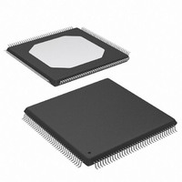
IC FPGA SPARTAN-3E 100K 144-TQFP
Manufacturer
Xilinx Inc
Series
Spartan™-3Er
Datasheet
1.XC3S100E-4TQG144I.pdf
(193 pages)
Specifications of XC3S100E-4TQG144I
Package / Case
144-TQFP, 144-VQFP
Mounting Type
Surface Mount
Voltage - Supply
1.1 V ~ 3.465 V
Operating Temperature
-40°C ~ 100°C
Number Of I /o
108
Number Of Logic Elements/cells
*
Number Of Gates
*
Lead Free Status / RoHS Status
Lead free / RoHS Compliant
Available stocks
Company
Part Number
Manufacturer
Quantity
Price
Company:

Part Number:
XC3S100E-4TQG144I
Manufacturer:
XILINX/21
Quantity:
163
Company:
Part Number:
XC3S100E-4TQG144I
Manufacturer:
Xilinx Inc
Quantity:
10 000
Part Number:
XC3S100E-4TQG144I
Manufacturer:
XILINX/赛灵思
Quantity:
20 000


Table 5: General DC Characteristics of User I/O, Dual-Purpose, and Dedicated Pins
DS312-3 (v1.0) March 1, 2005
Advance Product Specification
Notes:
1.
2.
3.
Symbol
I
I
RPU
RPD
I
I
C
REF
L
The numbers in this table are based on the conditions set forth in
The I
and maximum values
before applying V
unpowered, the impedance at the I/O pins is high.
This parameter is based on characterization. The pull-up resistance R
(2)
IN
(3)
(3)
L
specification applies to every I/O pin throughout power-on as long as the voltage on that pin stays between the absolute V
Leakage current at User I/O,
Dual-Purpose, and Dedicated pins
Current through pull-up resistor at
User I/O, Dual-Purpose, and
Dedicated pins
Current through pull-down resistor at
User I/O, Dual-Purpose, and
Dedicated pins
V
Input capacitance
R
REF
current per pin
CCO
(Table
power. Also consider applying V
Description
1). For hot-swap applications, at the time of card connection, be sure to keep all I/O voltages within this range
CCO
V
Driver is in a high-impedance state,
IN
www.xilinx.com
power before the connection of data lines occurs. When the FPGA is completely
= 0V or V
V
V
V
V
V
V
IN
IN
IN
IN
IN
IN
Table
Test Conditions
All V
= 0V, V
= 0V, V
= 0V, V
= 0V, V
= 0V, V
= 0V, V
PU
V
CCO
4.
IN
= V
CCO
= V
max, sample-tested
CCO
CCO
CCO
CCO
CCO
CCO
CCO
CCO
levels
/ I
= 3.3V
= 3.0V
= 2.5V
= 1.8V
= 1.5V
= 1.2V
RPU
. The pull-down resistance R
DC and Switching Characteristics
Min
–10
–10
3
Typ
-
-
-
PD
= V
Max
+10
+10
IN
10
/ I
IN
RPD
minimum
.
Units
mA
mA
mA
mA
mA
mA
mA
µA
µA
pF
3
Related parts for XC3S100E-4TQG144I
Image
Part Number
Description
Manufacturer
Datasheet
Request
R

Part Number:
Description:
IC SPARTAN-3E FPGA 100K 144-TQFP
Manufacturer:
Xilinx Inc
Datasheet:

Part Number:
Description:
FIELD PROGRAMMER
Manufacturer:
Xilinx Inc
Datasheet:
Part Number:
Description:
FPGA Spartan®-3E Family 100K Gates 2160 Cells 572MHz 90nm (CMOS) Technology 1.2V 100-Pin VTQFP
Manufacturer:
Xilinx Inc
Datasheet:

Part Number:
Description:
FPGA Spartan®-3E Family 100K Gates 2160 Cells 572MHz 90nm (CMOS) Technology 1.2V 144-Pin TQFP
Manufacturer:
Xilinx Inc
Datasheet:
Part Number:
Description:
FPGA Spartan®-3E Family 100K Gates 2160 Cells 657MHz 90nm (CMOS) Technology 1.2V 144-Pin TQFP
Manufacturer:
Xilinx Inc
Datasheet:
Part Number:
Description:
Spartan-3E FPGA Family
Manufacturer:
XILINX [Xilinx, Inc]
Datasheet:
Part Number:
Description:
Spartan-3E FPGA Family: Complete Data Sheet
Manufacturer:
XILINX [Xilinx, Inc]
Datasheet:
Part Number:
Description:
IC FPGA SPARTAN-3E 100K 100-VQFP
Manufacturer:
Xilinx Inc
Datasheet:

Part Number:
Description:
IC FPGA SPARTAN-3E 100K 132CSBGA
Manufacturer:
Xilinx Inc
Datasheet:
Part Number:
Description:
IC FPGA SPARTAN-3E 100K 132CSBGA
Manufacturer:
Xilinx Inc
Datasheet:
Part Number:
Description:
IC FPGA SPARTAN-3E 100K 144-TQFP
Manufacturer:
Xilinx Inc
Datasheet:
Part Number:
Description:
IC FPGA SPARTAN 3E 100VQFP
Manufacturer:
Xilinx Inc
Datasheet:
Part Number:
Description:
IC FPGA SPARTAN 3E 144TQFP
Manufacturer:
Xilinx Inc
Datasheet:
Part Number:
Description:
FPGA Spartan®-3E Family 100K Gates 2160 Cells 572MHz 90nm (CMOS) Technology 1.2V 132-Pin CSBGA
Manufacturer:
Xilinx Inc
Datasheet:

Part Number:
Description:
IC CPLD .8K 36MCELL 44-VQFP
Manufacturer:
Xilinx Inc
Datasheet: