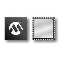
PIC16F1937-E/MV Microchip Technology, PIC16F1937-E/MV Datasheet - Page 467

PIC16F1937-E/MV
Manufacturer Part Number
PIC16F1937-E/MV
Description
14KB Flash, 512B RAM, 256B EEPROM, LCD, 1.8-5.5V 40 UQFN 5x5x0.5mm TUBE
Manufacturer
Microchip Technology
Series
PIC® XLP™ 16Fr
Datasheet
1.PIC16F1937-EMV.pdf
(472 pages)
Specifications of PIC16F1937-E/MV
Processor Series
PIC16F
Core
PIC
Program Memory Type
Flash
Program Memory Size
14 KB
Data Ram Size
256 B
Interface Type
MI2C, SPI, EUSART
Number Of Timers
5
Operating Supply Voltage
1.8 V to 5.5 V
Maximum Operating Temperature
+ 125 C
Mounting Style
SMD/SMT
Package / Case
UQFN-40
Development Tools By Supplier
MPLAB IDE Software
Minimum Operating Temperature
- 40 C
Core Processor
PIC
Core Size
8-Bit
Speed
32MHz
Connectivity
I²C, LIN, SPI, UART/USART
Peripherals
Brown-out Detect/Reset, LCD, POR, PWM, WDT
Number Of I /o
36
Eeprom Size
256 x 8
Ram Size
512 x 8
Voltage - Supply (vcc/vdd)
1.8 V ~ 5.5 V
Data Converters
A/D 14x10b
Oscillator Type
Internal
Operating Temperature
-40°C ~ 125°C
Lead Free Status / Rohs Status
Details
- Current page: 467 of 472
- Download datasheet (5Mb)
Timing Diagrams and Specifications
Timing Parameter Symbology........................................... 395
Timing Requirements
TMR0 Register .................................................................... 39
TMR1H Register ................................................................. 39
TMR1L Register .................................................................. 39
TMR2 Register .............................................................. 39, 47
TRIS .................................................................................. 380
TRISA Register ........................................................... 40, 135
TRISB ............................................................................... 138
TRISB Register ........................................................... 40, 140
TRISC ............................................................................... 143
TRISC Register ........................................................... 40, 144
TRISD ............................................................................... 146
TRISD Register ........................................................... 40, 147
TRISE ............................................................................... 149
TRISE Register ........................................................... 40, 150
Two-Speed Clock Start-up Mode ........................................ 79
TXCON (Timer2/4/6) Register .......................................... 211
TXREG.............................................................................. 295
TXREG Register ................................................................. 42
TXSTA Register .......................................................... 42, 302
U
USART
V
V
2008-2011 Microchip Technology Inc.
REF
SPI Slave Mode (CKE = 1) ....................................... 408
Synchronous Reception (Master Mode, SREN) ....... 317
Synchronous Transmission....................................... 315
Synchronous Transmission (Through TXEN) ........... 315
Timer0 and Timer1 External Clock ........................... 401
Timer1 Incrementing Edge........................................ 201
Two Speed Start-up .................................................... 80
Type-A in 1/2 MUX, 1/2 Bias Drive ........................... 347
Type-A in 1/2 MUX, 1/3 Bias Drive ........................... 349
Type-A in 1/3 MUX, 1/2 Bias Drive ........................... 351
Type-A in 1/3 MUX, 1/3 Bias Drive ........................... 353
Type-A in 1/4 MUX, 1/3 Bias Drive ........................... 355
Type-A/Type-B in Static Drive................................... 346
Type-B in 1/2 MUX, 1/2 Bias Drive ........................... 348
Type-B in 1/2 MUX, 1/3 Bias Drive ........................... 350
Type-B in 1/3 MUX, 1/2 Bias Drive ........................... 352
Type-B in 1/3 MUX, 1/3 Bias Drive ........................... 354
Type-B in 1/4 MUX, 1/3 Bias Drive ........................... 356
USART Synchronous Receive (Master/Slave) ......... 406
USART Synchronous Transmission (Master/Slave) . 405
Wake-up from Interrupt ............................................. 112
PLL Clock.................................................................. 397
I
I2C Bus Start/Stop Bits ............................................. 410
SPI Mode .................................................................. 409
BRGH Bit .................................................................. 305
Synchronous Master Mode
. S
2
C Bus Data ............................................................. 411
EE
Requirements, Synchronous Receive .............. 406
Requirements, Synchronous Transmission ...... 406
Timing Diagram, Synchronous Receive ........... 406
Timing Diagram, Synchronous Transmission ... 405
ADC Reference Voltage
W
Wake-up on Break ............................................................ 311
Wake-up Using Interrupts ................................................. 112
Watchdog Timer (WDT)...................................................... 90
WCOL ....................................................... 273, 276, 278, 280
WCOL Status Flag.................................... 273, 276, 278, 280
WDTCON Register ........................................................... 115
WPUB Register................................................................. 141
Write Protection .................................................................. 65
WWW Address ................................................................. 471
WWW, On-Line Support ..................................................... 14
Associated Registers................................................ 116
Configuration Word w/ Watchdog Timer................... 116
Modes....................................................................... 114
Specifications ........................................................... 401
PIC16(L)F1934/6/7
DS41364E-page 467
Related parts for PIC16F1937-E/MV
Image
Part Number
Description
Manufacturer
Datasheet
Request
R

Part Number:
Description:
IC, 8BIT MCU, PIC16F, 32MHZ, SOIC-18
Manufacturer:
Microchip Technology
Datasheet:

Part Number:
Description:
IC, 8BIT MCU, PIC16F, 32MHZ, SSOP-20
Manufacturer:
Microchip Technology
Datasheet:

Part Number:
Description:
IC, 8BIT MCU, PIC16F, 32MHZ, DIP-18
Manufacturer:
Microchip Technology
Datasheet:

Part Number:
Description:
IC, 8BIT MCU, PIC16F, 32MHZ, QFN-28
Manufacturer:
Microchip Technology
Datasheet:

Part Number:
Description:
IC, 8BIT MCU, PIC16F, 32MHZ, QFN-28
Manufacturer:
Microchip Technology
Datasheet:

Part Number:
Description:
IC, 8BIT MCU, PIC16F, 32MHZ, QFN-28
Manufacturer:
Microchip Technology
Datasheet:

Part Number:
Description:
IC, 8BIT MCU, PIC16F, 32MHZ, SSOP-20
Manufacturer:
Microchip Technology
Datasheet:

Part Number:
Description:
IC, 8BIT MCU, PIC16F, 20MHZ, DIP-40
Manufacturer:
Microchip Technology
Datasheet:

Part Number:
Description:
IC, 8BIT MCU, PIC16F, 32MHZ, QFN-28
Manufacturer:
Microchip Technology
Datasheet:

Part Number:
Description:
IC, 8BIT MCU, PIC16F, 20MHZ, MQFP-44
Manufacturer:
Microchip Technology
Datasheet:

Part Number:
Description:
IC, 8BIT MCU, PIC16F, 20MHZ, QFN-20
Manufacturer:
Microchip Technology
Datasheet:

Part Number:
Description:
IC, 8BIT MCU, PIC16F, 32MHZ, QFN-28
Manufacturer:
Microchip Technology
Datasheet:

Part Number:
Description:
MCU 14KB FLASH 768B RAM 64-TQFP
Manufacturer:
Microchip Technology
Datasheet:

Part Number:
Description:
7 KB Flash, 384 Bytes RAM, 32 MHz Int. Osc, 16 I/0, Enhanced Mid Range Core, Low
Manufacturer:
Microchip Technology

Part Number:
Description:
14KB Flash, 512B RAM, 256B EEPROM, LCD, 1.8-5.5V 40 UQFN 5x5x0.5mm TUBE
Manufacturer:
Microchip Technology


