MICRF405YML TR Micrel Inc, MICRF405YML TR Datasheet - Page 39
MICRF405YML TR
Manufacturer Part Number
MICRF405YML TR
Description
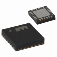
868-915 MHz ISM Band Transmitter
Manufacturer
Micrel Inc
Datasheet
1.MICRF405YML_TR.pdf
(46 pages)
Specifications of MICRF405YML TR
Frequency
290MHz ~ 980MHz
Applications
ISM
Modulation Or Protocol
ASK, FSK
Data Rate - Maximum
200 kbps
Power - Output
10dBm
Current - Transmitting
18mA
Data Interface
PCB, Surface Mount
Antenna Connector
PCB, Surface Mount
Voltage - Supply
2.2 V ~ 3.6 V
Operating Temperature
-40°C ~ 125°C
Package / Case
24-MLF®, QFN
Operating Temperature (min)
-40C
Operating Temperature (max)
125C
Operating Temperature Classification
Automotive
Product Depth (mm)
4mm
Product Length (mm)
4mm
Operating Supply Voltage (typ)
2.5/3.3V
Operating Supply Voltage (max)
3.6V
Lead Free Status / RoHS Status
Lead free / RoHS Compliant
Features
-
Memory Size
-
Lead Free Status / Rohs Status
Compliant
Other names
576-1965-2
MICRF405YMLTR
MICRF405YMLTR
MICRF405YMLTR
MICRF405YMLTR


April 2006
(**): When VCO_IB=000b, the bias current is set automatically by the two VCO_freq bit.
Micrel
FSKClk_K
ASKClk_K
MOD_F
VCO_by
ASK_PN_en
VCO_IB2
ASKn
FSKn
1..63
0..3
0..5
0..3
1..63
0
1
1
1
0
0
0
1
State
VCO is active
VCO is bypassed
Comments
Programmable smoothing filter after attenuator. This can be programmed in four steps, and will produce
reasonable results for the highest bit rates.
Comments
The bit rate clock is set by dividing the crystal oscillator frequency by FSKClk_K*2^(3+FSKn).
Comments
The crystal oscillator is divided by this number to produce modulator clock and it is divided further down by
2^(3+FSKn) to produce the bit rate clock.
Comments
The ASK bitrate clock is set by dividing the crystal oscillator frequency by ASKClk_K*2^(5+ASKn)
Comments
The crystal oscillator is divided by this number and is divided further down by 2^(5+ASKn) to produce the
ASK bitrate clock.
VCO_IB1
Comments
01010101…pattern is used in the FSK spreader during ASK.
111101011001000 repeated pattern is used in the FSK spreader during ASK.
1
0
1
0
VCO_IB0
1
1
1
0
Table 44. Modulator and Bit Rate Clock Setting.
Table 46. Modulator and Bit Rate Clock Setting.
Table 42. Modulator Filter Setting.
Comment
When VCO is bypassed, a differential signal can be applied to the circuit using
pin CPOUT and VARIN
Comments
Bias setting for VCO_Freq=0/1, 860 MHz
Bias setting for VCO_Freq=2/3, 868 MHz
Bias setting for VCO_Freq=4/5, 915 MHz
Bias setting for VCO_Freq=6/7, 950 MHz (**)
Table 49. VCO Bypass Bit.
Table 43. Bit Rate Setting.
Table 45. Bit Rate Setting.
Table 47. ASK Spreading.
Table 48. VCO Bias Bit.
39
MICRF405
(408) 955-1690
M9999-041906
Related parts for MICRF405YML TR
Image
Part Number
Description
Manufacturer
Datasheet
Request
R

Part Number:
Description:
MICRF405 Eval Board For Experimental Use Only
Manufacturer:
Micrel Inc
Part Number:
Description:
MICRF405 Eval Board For Experimental Use Only
Manufacturer:
Micrel Inc
Part Number:
Description:
MICRF405 Eval Board For Experimental Use Only
Manufacturer:
Micrel Inc
Part Number:
Description:
MICRF405 Eval Board For Experimental Use Only
Manufacturer:
Micrel Inc
Part Number:
Description:
Manufacturer:
Micrel Inc
Datasheet:
Part Number:
Description:
Manufacturer:
Micrel Inc
Datasheet:
Part Number:
Description:
Manufacturer:
Micrel Inc
Datasheet:
Part Number:
Description:
Manufacturer:
Micrel Inc
Datasheet:
Part Number:
Description:
Manufacturer:
Micrel Inc
Datasheet:
Part Number:
Description:
Manufacturer:
Micrel Inc
Datasheet:
Part Number:
Description:
Manufacturer:
Micrel Inc
Datasheet:
Part Number:
Description:
Manufacturer:
Micrel Inc
Datasheet:
Part Number:
Description:
Manufacturer:
Micrel Inc
Datasheet:
Part Number:
Description:
Manufacturer:
Micrel Inc
Datasheet: