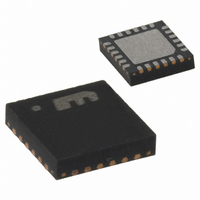
MICRF405YML TR Micrel Inc, MICRF405YML TR Datasheet - Page 21

MICRF405YML TR
Manufacturer Part Number
MICRF405YML TR
Description
868-915 MHz ISM Band Transmitter
Manufacturer
Micrel Inc
Datasheet
1.MICRF405YML_TR.pdf
(46 pages)
Specifications of MICRF405YML TR
Frequency
290MHz ~ 980MHz
Applications
ISM
Modulation Or Protocol
ASK, FSK
Data Rate - Maximum
200 kbps
Power - Output
10dBm
Current - Transmitting
18mA
Data Interface
PCB, Surface Mount
Antenna Connector
PCB, Surface Mount
Voltage - Supply
2.2 V ~ 3.6 V
Operating Temperature
-40°C ~ 125°C
Package / Case
24-MLF®, QFN
Operating Temperature (min)
-40C
Operating Temperature (max)
125C
Operating Temperature Classification
Automotive
Product Depth (mm)
4mm
Product Length (mm)
4mm
Operating Supply Voltage (typ)
2.5/3.3V
Operating Supply Voltage (max)
3.6V
Lead Free Status / RoHS Status
Lead free / RoHS Compliant
Features
-
Memory Size
-
Lead Free Status / Rohs Status
Compliant
Other names
576-1965-2
MICRF405YMLTR
MICRF405YMLTR
MICRF405YMLTR
MICRF405YMLTR
April 2006
Crystal Oscillator (XCO)
The crystal oscillator is a very critical block. As the
crystal oscillator is a reference for the RF output
frequency, very good phase and frequency stability
is required. When selecting crystal it should be paid
special attention to the total frequency tolerance and
load capacitance as these will directly influence on
the carrier frequency.
The crystal should be connected between pins XTA
and XTB (pin 7 and 8). MICRF405 has an internal
crystal capacitor bank used for crystal tolerance
tuning during production. These internal capacitors
can be enabled using the XCOtune[4:0] bits. If
XCOtune[4:0]=0 then no internal capacitors are
connected to the crystal pins, while 18pF are
connected to each pin if XCOtune[4:0]=31. The unit
capacitance is about 0.6pF. The internal XCOtune
feature is optimized for a crystal with a load
capacitance of 9pF and will give the expected
oscillation frequency when no external capacitors
are connected and XCOtune[4:0]=16. If a crystal
requires
0010101 ClkOut_1=0 ClkOut_0=0 XCO_Fast=1
Micrel
A6..A0
Adr
Figure 9. Crystal Oscillator Circuit.
D7
higher
XTB, pin 7
C1
D6
load
capacitance,
C2
D5
XTA, pin 8
XCOtune4=1
D4
additional
XCOtune3=0
D3
21
Data
capacitors must be added off-chip (C1 and C2 in
Figure 9).
If XCOtune[4:0]=0, the loading capacitors can be
calculated by the following formula;
The
capacitance and PCB stray capacitance. Typically
the total parasitic capacitance is around 6pF. For
instance, for a 9pF load crystal the recommended
values of the external load capacitors are 5.6pF.
The start-up time of a crystal oscillator is typically
around a millisecond. Therefore, to save current
consumption, the XCO is turned on before any other
circuit block. During start-up the XCO amplitude will
eventually reach a sufficient level to trigger the M-
counter. After counting 2 M-counter output pulses
the rest of the circuit will be turned on. The current
consumption during the prestart period is typically
205µA. If the XCO_Fast bit is set, then XCO will
start up faster, typically in about 300µs. This comes
at the expense of a higher current consumption of
typically 2mA during the period from start up until the
first output pulse of the M-divider.
If an external reference shall be used instead of a
crystal, the signal shall be applied to pin 7, XTB.
Due
recommended
reference and the XTB-pin.
XCOtune2=0
C
L
D2
=
parasitic
to
C
1
1
+
1
internal
C
1
2
XCOtune1=0
+
for
capacitance
C
D1
parasitic
use
biasing,
between
is
AC
XCOtune0=0
the
the
D0
coupling
MICRF405
(408) 955-1690
pin
M9999-041906
external
input
is


