MICRF405YML TR Micrel Inc, MICRF405YML TR Datasheet - Page 24
MICRF405YML TR
Manufacturer Part Number
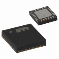
MICRF405YML TR
Description
868-915 MHz ISM Band Transmitter
Manufacturer
Micrel Inc
Datasheet
1.MICRF405YML_TR.pdf
(46 pages)
Specifications of MICRF405YML TR
Frequency
290MHz ~ 980MHz
Applications
ISM
Modulation Or Protocol
ASK, FSK
Data Rate - Maximum
200 kbps
Power - Output
10dBm
Current - Transmitting
18mA
Data Interface
PCB, Surface Mount
Antenna Connector
PCB, Surface Mount
Voltage - Supply
2.2 V ~ 3.6 V
Operating Temperature
-40°C ~ 125°C
Package / Case
24-MLF®, QFN
Operating Temperature (min)
-40C
Operating Temperature (max)
125C
Operating Temperature Classification
Automotive
Product Depth (mm)
4mm
Product Length (mm)
4mm
Operating Supply Voltage (typ)
2.5/3.3V
Operating Supply Voltage (max)
3.6V
Lead Free Status / RoHS Status
Lead free / RoHS Compliant
Features
-
Memory Size
-
Lead Free Status / Rohs Status
Compliant
Other names
576-1965-2
MICRF405YMLTR
MICRF405YMLTR
MICRF405YMLTR
MICRF405YMLTR


April 2006
Charge Pump and PLL Filter
There are two charge pumps, one for the external
loop filter, and one for the internal filter. Both pumps
have four different output current steps controlled by
the CP_CUR[1:0] bits (refer to Table 16). The
internal loop filter is a dual path type, which needs
two charge pump currents. The different steps allow
different bandwidths for the internal filter and give
greater flexibility when choosing components for the
external filter.
An external PLL loop filter is recommended when
using FSK modulation that is applied with dividers
and closed loop modulation using the modulator. For
Open Loop modulation a combination of external
and internal loop filter is recommended. In all modes
of ASK/OOK modulation, it is only possible to use
internal PLL loop filter due to the high bandwidth
requirements.
Table 15 below shows three different loop filters, the
three first are for closed loop modulation and the last
one is for open loop modulation. The component
values are calculated with RF frequency = 915MHz,
VCO gain = 67MHz/V and charge pump current =
100uA. Other settings are also shown in Table 15.
The varactor pin capacitance of 10-12pF does not
influence on the component values for the two filters
with lowest bandwidth. For the 12kHz bandwidth
filter, a third order loop filter is calculated. The third
pole is set by R2 and⋅C3. Here C3 is chosen to be
12pF,
capacitance. C3 can therefore be skipped.
Micrel
0010011
0010100
0010110
A6..A0
CP_CUR1
Adr
0
0
1
1
the
INT_LF_TEST=0
LF_High_PM=1
INT_LF_EN=1
same
D7
CP_CUR0
0
1
0
1
as
CP_CUR1=0
LF_CAP1=1
VCO_IB2=0
the
D6
External Charge Pump Current
12.5µA
25µA
50µA
100µA
varactor
CP_CUR0=1
LF_CAP0=1
VCO_IB1=0
D5
input
Table 16. Charge Pump.
pin
LF_RES1_4=0
LF_RES3_4=0
VCO_IB0=0
D4
24
Data
A schematic for a third order loop filter is shown in
Figure 11a. For a second order filter, C3 is not
connected and R2 is 0 Ω. When designing a third
order loop filter, the internal capacitance on the
VARIN pin of approximately 10-12pF must be taken
into consideration. Figure 11b shows the loop filter
configuration for the open loop VCO modulation
case.
The on-chip dual path filter is shown in Figure 11c.
The
configurable in four steps, by the LF_CAP[1:0] bits.
The ratio between C1 and C2 in Figure 11 c) sets
the phase margin of the filter. If LF_High_PM bit is
not set the phase margin is 56°, if it is set the phase
margin is 69°. The R1 and R3 resistor value is set
separately in 32 steps by the LF_RES1[4:0] and
LF_RES3[4:0] bits.
The on-chip dual path filter can be used when the
modulation type is set to Open-Loop VCO or ASK.
Table 18 gives the recommended settings for the
internal component values for various bitrates and
phase detector frequencies. The settings are
calculated to give optimal phase margin for the given
phase-frequency-detector frequency and loop filter
bandwidth. (More values of C and R can be found in
Table 52 and Table 52 on page 40 and 41).
LF_RES1_3=1
LF_RES3_3=0
VCO_by=0
D3
dual
Internal Charge Pump Current
1.25/12.5µA
3.125/31.25µA
6.25/62.5µA
12.5/125µA
path
LF_RES1_2=0
LF_RES3_2=1
OUTS2=0
D2
loop
filter
LF_RES1_1=0
LF_RES3_1=0
OUTS1=0
D1
has
MICRF405
capacitance
LF_RES1_0=1
LF_RES3_0=1
(408) 955-1690
M9999-041906
OUTS0=0
D0
Related parts for MICRF405YML TR
Image
Part Number
Description
Manufacturer
Datasheet
Request
R

Part Number:
Description:
MICRF405 Eval Board For Experimental Use Only
Manufacturer:
Micrel Inc
Part Number:
Description:
MICRF405 Eval Board For Experimental Use Only
Manufacturer:
Micrel Inc
Part Number:
Description:
MICRF405 Eval Board For Experimental Use Only
Manufacturer:
Micrel Inc
Part Number:
Description:
MICRF405 Eval Board For Experimental Use Only
Manufacturer:
Micrel Inc
Part Number:
Description:
Manufacturer:
Micrel Inc
Datasheet:
Part Number:
Description:
Manufacturer:
Micrel Inc
Datasheet:
Part Number:
Description:
Manufacturer:
Micrel Inc
Datasheet:
Part Number:
Description:
Manufacturer:
Micrel Inc
Datasheet:
Part Number:
Description:
Manufacturer:
Micrel Inc
Datasheet:
Part Number:
Description:
Manufacturer:
Micrel Inc
Datasheet:
Part Number:
Description:
Manufacturer:
Micrel Inc
Datasheet:
Part Number:
Description:
Manufacturer:
Micrel Inc
Datasheet:
Part Number:
Description:
Manufacturer:
Micrel Inc
Datasheet:
Part Number:
Description:
Manufacturer:
Micrel Inc
Datasheet: