MICRF405YML TR Micrel Inc, MICRF405YML TR Datasheet - Page 31
MICRF405YML TR
Manufacturer Part Number
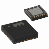
MICRF405YML TR
Description
868-915 MHz ISM Band Transmitter
Manufacturer
Micrel Inc
Datasheet
1.MICRF405YML_TR.pdf
(46 pages)
Specifications of MICRF405YML TR
Frequency
290MHz ~ 980MHz
Applications
ISM
Modulation Or Protocol
ASK, FSK
Data Rate - Maximum
200 kbps
Power - Output
10dBm
Current - Transmitting
18mA
Data Interface
PCB, Surface Mount
Antenna Connector
PCB, Surface Mount
Voltage - Supply
2.2 V ~ 3.6 V
Operating Temperature
-40°C ~ 125°C
Package / Case
24-MLF®, QFN
Operating Temperature (min)
-40C
Operating Temperature (max)
125C
Operating Temperature Classification
Automotive
Product Depth (mm)
4mm
Product Length (mm)
4mm
Operating Supply Voltage (typ)
2.5/3.3V
Operating Supply Voltage (max)
3.6V
Lead Free Status / RoHS Status
Lead free / RoHS Compliant
Features
-
Memory Size
-
Lead Free Status / Rohs Status
Compliant
Other names
576-1965-2
MICRF405YMLTR
MICRF405YMLTR
MICRF405YMLTR
MICRF405YMLTR


April 2006
The two first blocks are generating a clock for the
modulator. This clock is, together with the user data,
used to control a charge pump. The charge pump
current is controlled by a DAC. Each time the input
data changes state, a charge is then injected into
the capacitor to generate a modulation signal. The
charge magnitude is controlled by the charging
current and by charging time (inversely proportional
with modulator clock). To be able to achieve small
deviations, it is possible to attenuate the modulation
signal. Finally, the signal is filtered to narrow
transmitter output spectrum.
The procedure is first to determine the settings
concerning the data bit rate, then, these values will
be used in the calculation of the frequency deviation.
Finally, the user must see if the desired values
cause the modulator to saturate.
Deviation Setting
Deviation controlled by user parameters FSKClk_K,
MOD_I,
parameters fXTAL and KVCO. All user parameters
can be set in software, and fXTAL (crystal oscillator
frequency) is set when designing in the radio chip.
KVCO (VCO gain) is a parameter of the radio chip,
and is not controllable by the user.
The crystal oscillator frequency, fXTAL, is divided by
FSKClk_K to generate the modulator clock. Since
this modulator clock is controlling the rise and fall
times for the modulator, the frequency deviation is
inversely proportional to this clock. The relationship
is shown in equation (3):
It is assumed that FSKClk_K will be constant for
most applications to keep bit-rate and shaping
constant, although this is not a requirement.
The primary two controls of frequency deviation are
MOD_I and MOD_A. Of these two, MOD_I is the
parameter that controls the signal generation, while
MOD_A controls attenuation of this signal. The
reason for using an attenuator is to be able to
generate small deviations at high values of
FSKClk_K. The relationship is shown in equation
(4).
Finally, the VCO gain is given by equation (5).
Micrel
where:
Const1
f
f
K
DEV
DEV
VCO
∝
∝
=
−
and
FSKClk_K
2
MOD
Const
30
MOD
f
XTAL
.
6324
MOD_A,
_
_
1
A
I
+
×
(
Const
10
3
9
−
FreqBand
2
together
⋅
f
C
⋅
(
3
−
FreqBand
with
physical
)
)
(3)
(4)
(5)
31
FreqBand: Frequency band.
In equation (5), it is evident that the VCO gain is
dependent of carrier frequency. MOD_I is probably
the best parameter to alter if counteracting this effect
if necessary.
Combining equations (3), (4), and (5) gives us an
expression for the frequency deviation:
Observe that equation (6) gives single-sided-
deviation. Peak-to-peak deviation is twice this value.
Shaping
The modulation waveform will be shaped due to the
charging and discharging of a capacitor. The
waveform looks like a Gaussian filtered signal with a
Bandwidth⋅Period-product, BT, given by:
It is evident from this that a low FSKn gives a low
shaping factor, and is thus preferred if it is possible
to choose FSKn freely.
In addition to this, it is possible to smooth the
modulator output in a programmable low-pass filter.
This filter is controlled by the parameter MOD_F.
The parameter should be set according to equation
(8).
Modulator Saturation
The modulator output voltage is generated by a
capacitor that is being charged. This means that
there is a risk of saturating the modulator if the
charge received by the capacitor is too large. Use
equation (9) to determine the maximum value of
MOD_I that can be used.
If it turns out that the MOD_I-range is too small for
your
decreasing FSKClk_K accordingly.
f
DEV
Const2
fC: Carrier frequency of the radio.
where:
BT: Shaping factor.
BT
MOD
MOD
0: 315MHz,
1: 433MHz and
2: 900MHz.
=
FSKClk_K
=
requirements,
_
_
f
2
XTAL
FSKn
I
F
54
≤
≤
7 .
⎛
⎜ ⎜
⎝
150
FSKClk_K
⋅
2
MOD
f
MOD
BR
XTAL
×
10
_
_
A
I
3
try
⋅
Const
⋅
28
increasing
1
×
+
10
(
Const
3
−
6
−
FreqBand
⎞
⎟ ⎟
⎠
2
+
⋅
f
C
1
⋅
MICRF405
FSKn
(
3
(408) 955-1690
M9999-041906
−
FreqBand
(7)
(8)
(9)
and
(6)
)
)
Related parts for MICRF405YML TR
Image
Part Number
Description
Manufacturer
Datasheet
Request
R

Part Number:
Description:
MICRF405 Eval Board For Experimental Use Only
Manufacturer:
Micrel Inc
Part Number:
Description:
MICRF405 Eval Board For Experimental Use Only
Manufacturer:
Micrel Inc
Part Number:
Description:
MICRF405 Eval Board For Experimental Use Only
Manufacturer:
Micrel Inc
Part Number:
Description:
MICRF405 Eval Board For Experimental Use Only
Manufacturer:
Micrel Inc
Part Number:
Description:
Manufacturer:
Micrel Inc
Datasheet:
Part Number:
Description:
Manufacturer:
Micrel Inc
Datasheet:
Part Number:
Description:
Manufacturer:
Micrel Inc
Datasheet:
Part Number:
Description:
Manufacturer:
Micrel Inc
Datasheet:
Part Number:
Description:
Manufacturer:
Micrel Inc
Datasheet:
Part Number:
Description:
Manufacturer:
Micrel Inc
Datasheet:
Part Number:
Description:
Manufacturer:
Micrel Inc
Datasheet:
Part Number:
Description:
Manufacturer:
Micrel Inc
Datasheet:
Part Number:
Description:
Manufacturer:
Micrel Inc
Datasheet:
Part Number:
Description:
Manufacturer:
Micrel Inc
Datasheet: