MICRF405YML TR Micrel Inc, MICRF405YML TR Datasheet - Page 18
MICRF405YML TR
Manufacturer Part Number
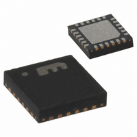
MICRF405YML TR
Description
868-915 MHz ISM Band Transmitter
Manufacturer
Micrel Inc
Datasheet
1.MICRF405YML_TR.pdf
(46 pages)
Specifications of MICRF405YML TR
Frequency
290MHz ~ 980MHz
Applications
ISM
Modulation Or Protocol
ASK, FSK
Data Rate - Maximum
200 kbps
Power - Output
10dBm
Current - Transmitting
18mA
Data Interface
PCB, Surface Mount
Antenna Connector
PCB, Surface Mount
Voltage - Supply
2.2 V ~ 3.6 V
Operating Temperature
-40°C ~ 125°C
Package / Case
24-MLF®, QFN
Operating Temperature (min)
-40C
Operating Temperature (max)
125C
Operating Temperature Classification
Automotive
Product Depth (mm)
4mm
Product Length (mm)
4mm
Operating Supply Voltage (typ)
2.5/3.3V
Operating Supply Voltage (max)
3.6V
Lead Free Status / RoHS Status
Lead free / RoHS Compliant
Features
-
Memory Size
-
Lead Free Status / Rohs Status
Compliant
Other names
576-1965-2
MICRF405YMLTR
MICRF405YMLTR
MICRF405YMLTR
MICRF405YMLTR


April 2006
Main Modes of Operation
There are three main modes of operation and these
are controlled by Mode1-0, see Table 9. In “Power
down” mode all blocks are shut down, though the
contents of the registers are preserved. In “Standby”
the crystal oscillator is running and an optional
programmable clock is present on the CLKOUT pin
(Default enabled). This clock can be used as a
micro-controller reference frequency. In “TX“ mode
all blocks are active if not disabled by the user.
Power Amplifier
The maximum output power is approximately
10dBm. For maximum output power the load seen
by the PA must be resistive and around 150Ω at
900MHz and 250Ω at 434MHz and 315Hz. The
output power can be programmed with bits PA[2:0]
to eight different levels if bit PA_LDc_en=1 or seven
levels if PA_LDc_en=0, with approximately 3dB
between each step. If PA_LDc_en=0, the PA is
turned of by setting PA[2:0] to 0. For all other
PA[2:0] combinations, the PA is on and has a
maximum power when PA[2:0]=7. If PA_LDc_en=1
the PA is controlled by the lock detector.
A simple π LC network can be used to provide the
0000000
0010111
Micrel
A6..A0
Adr
0000000
A6..A0
PA_IB3=1
Adr
Mode1=0
D7
Table 10. Recommended Settings of PA_IB and PAB_IB vs. Frequency Band.
PA_IB2 =0
Mode0=1
D6
Mode1=0
Frequency band
D7
(MHz)
315
434
868
915
Mode0=1
PA_IB1=0
PA2=1
D6
D5
PA2=1
D5
PA_IB0=1
PA_IB[2:0]
PA1=1
D4
PA1=1
10
D4
8
9
9
18
Data
needed impedance and also to reduce the power of
the harmonics to acceptable levels. Such matching
networks for different frequencies are shown on the
Typical Application Circuit.
The bias setting of the PA and the PA buffer is
controlled by bits PA_IB PA[2:0] and PAB_IB
PA[2:0]. The recommended bit setting, shown in
Table 10, is for the different frequency bands.
Typical
consumption for the different power levels for
different frequencies are shown in Table 11. The
settings used are: Modulation[2:0]=2, ClkOut_en=0,
external loop filter.
Mode1 Mode0
PA0=1
D3
PAB_IB3=1
0
0
1
1
PA0=1
D3
Data
PAB_IB[2:0]
ClkOut_en=1
values
Table 9. MICRF405 Main Modes.
0
1
0
1
D2
8
8
9
9
ClkOut_en=1
PAB_IB2=0
Transmit mode
Power down
of
Standby
D2
State
output power
Sync_en=1
D1
PAB_IB1=0
Sync_en=1
D1
Crystal Oscillator
Keeps Register
Transmit mode
configuration
Comments
running
Load_en=1
and current
MICRF405
D0
(408) 955-1690
M9999-041906
PAB_IB0=1
Load_en=1
D0
Related parts for MICRF405YML TR
Image
Part Number
Description
Manufacturer
Datasheet
Request
R

Part Number:
Description:
MICRF405 Eval Board For Experimental Use Only
Manufacturer:
Micrel Inc
Part Number:
Description:
MICRF405 Eval Board For Experimental Use Only
Manufacturer:
Micrel Inc
Part Number:
Description:
MICRF405 Eval Board For Experimental Use Only
Manufacturer:
Micrel Inc
Part Number:
Description:
MICRF405 Eval Board For Experimental Use Only
Manufacturer:
Micrel Inc
Part Number:
Description:
Manufacturer:
Micrel Inc
Datasheet:
Part Number:
Description:
Manufacturer:
Micrel Inc
Datasheet:
Part Number:
Description:
Manufacturer:
Micrel Inc
Datasheet:
Part Number:
Description:
Manufacturer:
Micrel Inc
Datasheet:
Part Number:
Description:
Manufacturer:
Micrel Inc
Datasheet:
Part Number:
Description:
Manufacturer:
Micrel Inc
Datasheet:
Part Number:
Description:
Manufacturer:
Micrel Inc
Datasheet:
Part Number:
Description:
Manufacturer:
Micrel Inc
Datasheet:
Part Number:
Description:
Manufacturer:
Micrel Inc
Datasheet:
Part Number:
Description:
Manufacturer:
Micrel Inc
Datasheet: