MICRF405YML TR Micrel Inc, MICRF405YML TR Datasheet - Page 7
MICRF405YML TR
Manufacturer Part Number
MICRF405YML TR
Description
868-915 MHz ISM Band Transmitter
Manufacturer
Micrel Inc
Datasheet
1.MICRF405YML_TR.pdf
(46 pages)
Specifications of MICRF405YML TR
Frequency
290MHz ~ 980MHz
Applications
ISM
Modulation Or Protocol
ASK, FSK
Data Rate - Maximum
200 kbps
Power - Output
10dBm
Current - Transmitting
18mA
Data Interface
PCB, Surface Mount
Antenna Connector
PCB, Surface Mount
Voltage - Supply
2.2 V ~ 3.6 V
Operating Temperature
-40°C ~ 125°C
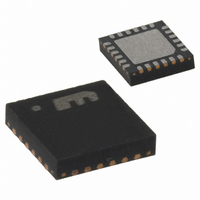
Package / Case
24-MLF®, QFN
Operating Temperature (min)
-40C
Operating Temperature (max)
125C
Operating Temperature Classification
Automotive
Product Depth (mm)
4mm
Product Length (mm)
4mm
Operating Supply Voltage (typ)
2.5/3.3V
Operating Supply Voltage (max)
3.6V
Lead Free Status / RoHS Status
Lead free / RoHS Compliant
Features
-
Memory Size
-
Lead Free Status / Rohs Status
Compliant
Other names
576-1965-2
MICRF405YMLTR
MICRF405YMLTR
MICRF405YMLTR
MICRF405YMLTR


April 2006
Data and Configuration Interface
The user interface of the MICRF405 is a serial
peripheral interface (SPI) consisting of Serial
interface enable (SEN), Serial data input/output
(SIO) and Serial clock (SCK). This user interface is
used for MICRF405 configuration setup and can
also be used for sending the user data. A second
option is to transmit data bitwise using the DATAIN
pin. The RDY/DATACLK pin is used to synchronize
the data transfers.
The control word consists of 30 addressable bytes
and defines the way of operations as well as
transmitting data. Table 1 shows all 30 bytes. The
values specified are the default setup, which are
preset after power up. The first register is the
Micrel
0000000
0000001
0000010
0000011
0000100
0000101
0000110
0000111
0001000
0001001
0001010
0001011
0001100 LowBatt_level=0
0001101
0001110
0001111
0010000
0010001
0010010
0010011
0010100
0010101
0010110 INT_LF_TEST=0
0010111
0011000
0011001
0011010
0011011
0011100
0011101
A6..A0
Adr
VCO_Fr_Chk=0
LF_High_PM=1
ASK_PN_en=0
LowBatt_en=1
INT_LF_EN=1
VCO_freq_O2
SyncID3_7=1
SyncID2_7=1
SyncID1_7=1
SyncID0_7=1
Bit_IO_en=1
ClkOut_1=0
Mod_I4=0
PA_IB3=1
ASKn1=1
Mode1=0
DATA_7
M0_7=0
M1_7=0
N0_7=0
N1_7=0
D7
0
-
-
-
-
-
-
Manchester_en=0
VCO_Fr_Auto=0
Prescaler_Sel=0
Freq_Band1=0
VCO_freq_O1
SyncID3_6=1
SyncID2_6=1
SyncID1_6=1
SyncID0_6=1
CP_CUR1=0
LF_CAP1=1
VCO_IB2=0
ClkOut_0=0
ASK_EN=0
LDO_by=0
PA_IB2 =0
Mod_I3=1
Mode0=1
ASKn0=0
DATA_6
N0_6=1
M0_6=0
N1_6=1
M1_6=0
Table 1. Controlword MICRF405 (values preset at power-up).
D6
-
-
-
-
-
-
Freq_Band0=1
ASKshape2=1
FSKClk_K5=1
ASKClk_K5=1
VCO_freq_O0
SyncID3_5=1
SyncID2_5=1
SyncID1_5=1
SyncID0_5=1
Sel_CRC1=1
CP_CUR0=1
XCO_Fast=1
LDO_en1=1
LF_CAP0=1
VCO_IB1=0
Mod_I2=0
PA_IB1=0
FSKn2=1
DATA_5
M0_5=1
M1_5=1
A0_5=0
N0_5=1
A1_5=0
N1_5=1
PA2=1
D5
-
-
-
-
LF_RES3_4=0
ASKshape1=1
LF_RES1_4=0
FSKClk_K4=1
ASKClk_K4=1
VCO_freq2=0
SyncID3_4=0
SyncID2_4=0
SyncID1_4=0
SyncID0_4=0
Sel_CRC0=1
XCOtune4=1
LDO_en0=1
VCO_IB0=0
Mod_I1=0
PA_IB0=1
FSKn1=0
DATA_4
M0_4=0
M1_4=0
A0_4=0
N0_4=1
A1_4=1
N1_4=0
PA1=1
D4
-
-
-
-
7
Data
desktop register controlling the state of the 405, the
PA and clock-out for the microcontroller. The next
block of 10bytes sets the output radio frequency
through the dividers A, N and M. The bytes with
address 11 to 21 set the frequency band, modulation
type, bit rate, loop filter type and bandwidth, XCO
tuning etc. This block is not frequently used as these
settings are usually static application dependent.
Address 22 and 23 are mostly test bits, and are
seldom altered from default settings in applications.
The interrupt register, which is located at address
24, is read only (writing to it will not do any harm or
have any effect). The last 5 bytes are used when
transferring user data to transmit through the SPI.
The first four set the SyncID field in the packet, and
the last is the one byte data buffer.
MOD_LDc_en=0
SyncID_Len1=0
LF_RES1_3=1
LF_RES3_3=0
ASKshape0=1
FSKClk_K3=0
ASKClk_K3=0
VCO_freq1=1
SyncID3_3=0
SyncID2_3=0
SyncID1_3=0
SyncID0_3=0
XCOtune3=0
PAB_IB3=1
VCO_by=0
Mod_I0=1
N0_11=0
M0_11=0
N1_11=0
M1_11=0
FSKn0=0
DATA_3
M0_3=0
M1_3=0
A0_3=1
N0_3=0
A1_3=1
N1_3=1
PA0=1
D3
SyncID_Len0=1
LF_RES1_2=0
LF_RES3_2=1
PA_FEc_en=0
ASKClk_K2=1
FSKClk_K2=1
VCO_freq0=1
SyncID3_2=1
SyncID2_2=1
SyncID1_2=1
SyncID0_2=1
ClkOut_en=1
XCOtune2=0
PAB_IB2=0
Mod_A2=0
Mod_F2=1
OUTS2=0
M0_10=0
M1_10=0
N0_10=0
N1_10=0
ASK2=1
DATA_2
M0_2=0
M1_2=0
A0_2=1
N0_2=0
A1_2=1
N1_2=1
VC_HI
D2
Pream_Len1=1
Modulation1=1
PA_LDc_en=0
LF_RES1_1=0
LF_RES3_1=0
FSKClk_K1=0
ASKClk_K1=0
SyncID3_1=0
SyncID2_1=0
SyncID1_1=0
SyncID0_1=0
XCOtune1=0
PAB_IB1=0
Sync_en=1
Mod_A1=1
Mod_F1=0
OUTS1=0
M0_9=0
M0_1=0
M1_9=0
M1_1=0
ASK1=1
DATA_1
A0_1=1
N0_9=0
N0_1=1
A1_1=1
N1_9=0
N1_1=1
VC_LO
D1
Pream_Len0=0
Modulation0=0
LF_RES1_0=1
LF_RES3_0=1
ASKClk_K0=0
FSKClk_K0=0
MICRF405
SyncID3_0=1
SyncID2_0=1
SyncID1_0=1
SyncID0_0=1
XCOtune0=0
LOW_BATT
PAB_IB0=1
Load_en=1
Mod_A0=1
Mod_F0=0
OUTS0=0
(408) 955-1690
LD_en=1
M9999-041906
DATA_0
M0_8=0
M0_0=1
M1_8=0
M1_0=0
ASK0=1
A0_0=0
N0_8=0
N0_0=1
A1_0=1
N1_8=0
N1_0=1
D0
Related parts for MICRF405YML TR
Image
Part Number
Description
Manufacturer
Datasheet
Request
R

Part Number:
Description:
MICRF405 Eval Board For Experimental Use Only
Manufacturer:
Micrel Inc
Part Number:
Description:
MICRF405 Eval Board For Experimental Use Only
Manufacturer:
Micrel Inc
Part Number:
Description:
MICRF405 Eval Board For Experimental Use Only
Manufacturer:
Micrel Inc
Part Number:
Description:
MICRF405 Eval Board For Experimental Use Only
Manufacturer:
Micrel Inc
Part Number:
Description:
Manufacturer:
Micrel Inc
Datasheet:
Part Number:
Description:
Manufacturer:
Micrel Inc
Datasheet:
Part Number:
Description:
Manufacturer:
Micrel Inc
Datasheet:
Part Number:
Description:
Manufacturer:
Micrel Inc
Datasheet:
Part Number:
Description:
Manufacturer:
Micrel Inc
Datasheet:
Part Number:
Description:
Manufacturer:
Micrel Inc
Datasheet:
Part Number:
Description:
Manufacturer:
Micrel Inc
Datasheet:
Part Number:
Description:
Manufacturer:
Micrel Inc
Datasheet:
Part Number:
Description:
Manufacturer:
Micrel Inc
Datasheet:
Part Number:
Description:
Manufacturer:
Micrel Inc
Datasheet: