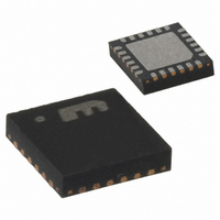
MICRF405YML TR Micrel Inc, MICRF405YML TR Datasheet - Page 2

MICRF405YML TR
Manufacturer Part Number
MICRF405YML TR
Description
868-915 MHz ISM Band Transmitter
Manufacturer
Micrel Inc
Datasheet
1.MICRF405YML_TR.pdf
(46 pages)
Specifications of MICRF405YML TR
Frequency
290MHz ~ 980MHz
Applications
ISM
Modulation Or Protocol
ASK, FSK
Data Rate - Maximum
200 kbps
Power - Output
10dBm
Current - Transmitting
18mA
Data Interface
PCB, Surface Mount
Antenna Connector
PCB, Surface Mount
Voltage - Supply
2.2 V ~ 3.6 V
Operating Temperature
-40°C ~ 125°C
Package / Case
24-MLF®, QFN
Operating Temperature (min)
-40C
Operating Temperature (max)
125C
Operating Temperature Classification
Automotive
Product Depth (mm)
4mm
Product Length (mm)
4mm
Operating Supply Voltage (typ)
2.5/3.3V
Operating Supply Voltage (max)
3.6V
Lead Free Status / RoHS Status
Lead free / RoHS Compliant
Features
-
Memory Size
-
Lead Free Status / Rohs Status
Compliant
Other names
576-1965-2
MICRF405YMLTR
MICRF405YMLTR
MICRF405YMLTR
MICRF405YMLTR
April 2006
Table of Contents
General Description ................................................................................................................................................................... 1
Features ..................................................................................................................................................................................... 1
Applications................................................................................................................................................................................ 1
Table of Contents....................................................................................................................................................................... 2
Ordering Information .................................................................................................................................................................. 3
Block Diagram............................................................................................................................................................................ 3
Pin Configuration........................................................................................................................................................................ 4
Absolute Maximum Ratings
Operating Ratings
Electrical Characteristics ............................................................................................................................................................ 5
Electrical Characteristics (cont.)................................................................................................................................................. 6
Data and Configuration Interface ............................................................................................................................................... 7
Data Interface and Data Transfer............................................................................................................................................. 13
Main Modes of Operation ......................................................................................................................................................... 18
Power Amplifier ........................................................................................................................................................................ 18
Frequency Synthesizer............................................................................................................................................................. 19
Crystal Oscillator (XCO) ........................................................................................................................................................... 21
VCO ......................................................................................................................................................................................... 22
Charge Pump and PLL Filter.................................................................................................................................................... 24
Modulation................................................................................................................................................................................ 27
Bit Description .......................................................................................................................................................................... 34
Typical Application Circuit ........................................................................................................................................................ 42
Package Information ................................................................................................................................................................ 45
Micrel
Programming Interface Timing .............................................................................................................................................. 8
Writing to the Control Registers in MICRF405....................................................................................................................... 9
What to write: ........................................................................................................................................................................ 9
How to write:.......................................................................................................................................................................... 9
The two different ways to “program the chip” are: ................................................................................................................. 9
Writing to a Single Register ................................................................................................................................................... 9
How to write:.......................................................................................................................................................................... 9
Writing to All Registers ........................................................................................................................................................ 10
What to write ....................................................................................................................................................................... 10
How to write:........................................................................................................................................................................ 10
Writing to n Registers Having Incremental Addresses......................................................................................................... 10
What to write ....................................................................................................................................................................... 11
Writing to n Registers Having Non-Incremental Addresses................................................................................................. 12
Reading from the Control Registers in MICRF405 .............................................................................................................. 12
Reading from the Interrupt Register .................................................................................................................................... 12
Packet Engine Overview: .................................................................................................................................................... 14
How to transmit a Packet with the Packet Engine: .............................................................................................................. 15
Programming Summary....................................................................................................................................................... 17
Bit rate settings.................................................................................................................................................................... 30
Modulator ............................................................................................................................................................................ 30
Deviation setting.................................................................................................................................................................. 31
Shaping ............................................................................................................................................................................... 31
Modulator saturation............................................................................................................................................................ 31
Lock Detect ......................................................................................................................................................................... 32
Low Dropout Regulator (LDO) and Low Battery Detector.................................................................................................... 33
(2)
................................................................................................................................................................... 5
(1)
..................................................................................................................................................... 5
2
MICRF405
(408) 955-1690
M9999-041906


