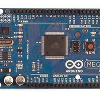
A000047 Arduino, A000047 Datasheet - Page 174

A000047
Manufacturer Part Number
A000047
Description
MCU, MPU & DSP Development Tools Mega2560
Manufacturer
Arduino
Series
-r
Type
MCUr
Specifications of A000047
Processor To Be Evaluated
ATmega2560
Interface Type
USB, I2C, SPI
Dimensions
4 in x 2.1 in
Operating Supply Voltage
5 V
Contents
Board
Lead Free Status / RoHS Status
Lead free / RoHS Compliant
For Use With/related Products
ATmega2560
- Current page: 174 of 444
- Download datasheet (10Mb)
19. 8-bit Timer/Counter2 with PWM and Asynchronous Operation
19.1
2549M–AVR–09/10
Overview
Timer/Counter2 is a general purpose, single channel, 8-bit Timer/Counter module. The main
features are:
•
•
•
•
•
•
•
A simplified block diagram of the 8-bit Timer/Counter is shown in Figure 16-12. For the actual
placement of I/O pins, see
ing I/O bits and I/O pins, are shown in bold. The device-specific I/O Register and bit locations
are listed in the
The Power Reduction Timer/Counter2 bit, PRTIM2, in
page 56
Figure 19-1. 8-bit Timer/Counter Block Diagram
Single Channel Counter
Clear Timer on Compare Match (Auto Reload)
Glitch-free, Phase Correct Pulse Width Modulator (PWM)
Frequency Generator
10-bit Clock Prescaler
Overflow and Compare Match Interrupt Sources (TOV2, OCF2A and OCF2B)
Allows Clocking from External 32 kHz Watch Crystal Independent of the I/O Clock
Status flags
must be written to zero to enable Timer/Counter2 module.
Timer/Counter
TCCRnA
OCRnA
TCNTn
“Register Description” on page
OCRnB
=
=
Direction
“Pin Configurations” on page
Count
Clear
ASSRn
Synchronized Status flags
ATmega640/1280/1281/2560/2561
Control Logic
TOP
=
TCCRnB
asynchronous mode
Value
BOTTOM
Fixed
TOP
select (ASn)
clk
=
Tn
0
187.
Prescaler
Synchronization Unit
“PRR0 – Power Reduction Register 0” on
2. CPU accessible I/O Registers, includ-
OCnA
(Int.Req.)
OCnB
(Int.Req.)
Generation
Generation
Waveform
Waveform
TOVn
(Int.Req.)
OCnA
OCnB
Oscillator
T/C
clk
I/O
clk
clk
I/O
ASY
TOSC1
TOSC2
174
Related parts for A000047
Image
Part Number
Description
Manufacturer
Datasheet
Request
R

Part Number:
Description:
Daughter Cards & OEM Boards ARDUINO UNO PROTO PCB REV 3
Manufacturer:
Arduino

Part Number:
Description:
Daughter Cards & OEM Boards ARDUINO SHIELD PROTO KIT REV 3
Manufacturer:
Arduino

Part Number:
Description:
Daughter Cards & OEM Boards ARDUINO MEGA PROTO KIT REV 3
Manufacturer:
Arduino

Part Number:
Description:
Daughter Cards & OEM Boards ARDUINO MEGA PROTO PCB REV 3
Manufacturer:
Arduino

Part Number:
Description:
Development Boards & Kits - AVR ARDUINO STARTER KIT W/ UNO REV3
Manufacturer:
Arduino

Part Number:
Description:
RF Development Tools ARDUINO SHIELD WIRELESS PROTO
Manufacturer:
Arduino
Datasheet:

Part Number:
Description:
RF Development Tools ARDUINO SHIELD WIRELESS WITH SD
Manufacturer:
Arduino
Datasheet:

Part Number:
Description:
Development Software Getting started w/Arduino
Manufacturer:
Arduino

Part Number:
Description:
Ethernet Modules & Development Tools Ethernet Shield for Arduino
Manufacturer:
Arduino

Part Number:
Description:
MCU, MPU & DSP Development Tools LilyPad Arduino Main Board
Manufacturer:
Arduino

Part Number:
Description:
ARDUINO NANO Board
Manufacturer:
Arduino
Datasheet:

Part Number:
Description:
Ethernet Modules & Development Tools ETHERNET SHEILD PoE FOR ARDUINO
Manufacturer:
Arduino
Datasheet:

Part Number:
Description:
ATMEGA328 MCU IC W/ Arduino UNO Bootloader
Manufacturer:
Arduino
Datasheet:

Part Number:
Description:
Memory Cards MICRO SD CARD 1GB WITH SD ADAPTER
Manufacturer:
Arduino


