FDME1034CZT Fairchild Semiconductor, FDME1034CZT Datasheet - Page 3
FDME1034CZT
Manufacturer Part Number
FDME1034CZT
Description
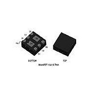
MOSFET N/P-CH 20V 6-MICROFET
Manufacturer
Fairchild Semiconductor
Series
PowerTrench®r
Datasheet
1.FDME1034CZT.pdf
(11 pages)
Specifications of FDME1034CZT
Fet Type
N and P-Channel
Fet Feature
Logic Level Gate
Rds On (max) @ Id, Vgs
66 mOhm @ 3.4A, 4.5V
Drain To Source Voltage (vdss)
20V
Current - Continuous Drain (id) @ 25° C
3.8A, 2.6A
Vgs(th) (max) @ Id
1V @ 250µA
Gate Charge (qg) @ Vgs
4.2nC @ 4.5V
Input Capacitance (ciss) @ Vds
300pF @ 10V
Power - Max
600mW
Mounting Type
Surface Mount
Package / Case
6-MLP, 6-MicroFET™
Configuration
Dual
Transistor Polarity
N and P-Channel
Resistance Drain-source Rds (on)
55 mOhms, 95 mOhms
Drain-source Breakdown Voltage
20 V, - 20 V
Continuous Drain Current
3.4 A, - 2.3 A
Power Dissipation
1.3 W
Maximum Operating Temperature
+ 150 C
Forward Transconductance Gfs (max / Min)
9 S, 7 S
Gate Charge Qg
3 nC, 5.5 nC
Minimum Operating Temperature
- 55 C
Mounting Style
SMD/SMT
Module Configuration
Dual
Continuous Drain Current Id
3.8A
Drain Source Voltage Vds
20V
On Resistance Rds(on)
0.055ohm
Rds(on) Test Voltage Vgs
4.5V
Rohs Compliant
Yes
Lead Free Status / RoHS Status
Lead free / RoHS Compliant
Available stocks
Company
Part Number
Manufacturer
Quantity
Price

Part Number:
FDME1034CZT
Manufacturer:
FAIRCHILD/仙童
Quantity:
20 000


FDME1034CZT Rev.C1
©2010 Fairchild Semiconductor Corporation
Electrical Characteristics
Drain-Source Diode Characteristics
Notes:
1. R
2. Pulse Test: Pulse Width < 300 μs, Duty cycle < 2.0%.
3. The diode connected between the gate and source serves only as protection ESD. No gate overvoltage rating is implied.
V
t
Q
rr
the user's board design.
SD
rr
Symbol
θJA
is determined with the device mounted on a 1 in
Source to Drain Diode Forward
Voltage
Reverse Recovery Time
Reverse Recovery Time
Parameter
a. 90 °C/W when mounted on
a 1 in
2
pad of 2 oz copper.
2
T
pad 2 oz copper pad on a 1.5 x 1.5 in. board of FR-4 material. R
J
= 25 °C unless otherwise noted
V
V
Q1
I
Q2
I
F
F
GS
GS
= 3.4 A, di/dt = 100 A/μS
= -2.3 A, di/dt = 100 A/μs
= 0 V, I
= 0 V, I
Test Conditions
S
S
= 0.9 A
= -0.9 A
3
(Note 2)
(Note 2)
Type
Q1
Q2
Q1
Q2
Q1
Q2
θJC
b. 195 °C/W when mounted on a
is guaranteed by design while R
minimum pad of 2 oz copper.
Min
-0.8
Typ
0.7
8.5
1.4
4.4
16
θCA
Max
-1.2
1.2
17
29
10
10
www.fairchildsemi.com
is determined by
Units
nC
ns
V
Related parts for FDME1034CZT
Image
Part Number
Description
Manufacturer
Datasheet
Request
R

Part Number:
Description:
Fairchild Semiconductor [IGBT MODULE]
Manufacturer:
Fairchild Semiconductor
Datasheet:

Part Number:
Description:
Discrete Semiconductor Modules
Manufacturer:
Fairchild Semiconductor
Part Number:
Description:
Discrete Semiconductor Modules
Manufacturer:
Fairchild Semiconductor
Part Number:
Description:
This N-Channel MOSFET is produced using Fairchild Semiconductor’s advanced Power Trench® process
Manufacturer:
Fairchild Semiconductor
Datasheet:
Part Number:
Description:
This N-Channel MOSFET is produced using Fairchild Semiconductor’s advanced Power Trench® process
Manufacturer:
Fairchild Semiconductor
Datasheet:
Part Number:
Description:
This N-Channel MOSFET is produced using Fairchild Semiconductor’s advanced PowerTrench® process
Manufacturer:
Fairchild Semiconductor
Datasheet:
Part Number:
Description:
This N-Channel MOSFET is produced using Fairchild Semiconductor’s advanced PowerTrench® process
Manufacturer:
Fairchild Semiconductor
Datasheet:
Part Number:
Description:
This N-Channel MOSFET is produced using Fairchild Semiconductor’s advanced Power Trench® process
Manufacturer:
Fairchild Semiconductor
Datasheet:
Part Number:
Description:
This N-Channel logic Level MOSFETs are produced using Fairchild Semiconductor‘s advanced Power Trench® process that has been special tailored to minimize the on-state resistance and yet maintain superior switching performance
Manufacturer:
Fairchild Semiconductor
Datasheet:
Part Number:
Description:
This N-Channel MOSFET is produced using Fairchild Semiconductor’s advanced Power Trench® process
Manufacturer:
Fairchild Semiconductor
Datasheet:
Part Number:
Description:
This N-Channel SyncFET™ is produced using Fairchild Semiconductor’s advanced PowerTrench® process
Manufacturer:
Fairchild Semiconductor
Datasheet:
Part Number:
Description:
This N-Channel SyncFET™ is produced using Fairchild Semiconductor’s advanced PowerTrench® process
Manufacturer:
Fairchild Semiconductor
Datasheet:
Part Number:
Description:
This N-Channel SyncFET™ is produced using Fairchild Semiconductor’s advanced PowerTrench® process
Manufacturer:
Fairchild Semiconductor
Datasheet:
Part Number:
Description:
This N-Channel logic Level MOSFETs are produced using Fairchild Semiconductor‘s advanced Power Trench® process that has been special tailored to minimize the on-state resistance and yet maintain superior switching performance
Manufacturer:
Fairchild Semiconductor
Datasheet:
Part Number:
Description:
This N-Channel MOSFET is produced using Fairchild Semiconductor’s advanced Power Trench® process that has been especially tailored to minimize the on-state resistance and yet maintain superior switching performance
Manufacturer:
Fairchild Semiconductor
Datasheet: