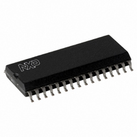
MFRC53101T/0FE,112 NXP Semiconductors, MFRC53101T/0FE,112 Datasheet - Page 24

MFRC53101T/0FE,112
Manufacturer Part Number
MFRC53101T/0FE,112
Description
IC MIFARE HS READER 32-SOIC
Manufacturer
NXP Semiconductors
Series
MIFARE®r
Specifications of MFRC53101T/0FE,112
Rf Type
Read Only
Frequency
13.56MHz
Features
ISO14443-A, ISO14443-B, ISO15693
Package / Case
32-SOIC (0.300", 7.50mm Width)
Product
RFID Readers
Operating Temperature Range
- 25 C to + 85 C
Lead Free Status / RoHS Status
Lead free / RoHS Compliant
Lead Free Status / RoHS Status
Lead free / RoHS Compliant, Lead free / RoHS Compliant
Other names
568-2224-5
935269691112
MFRC531
MFRC53101TD
935269691112
MFRC531
MFRC53101TD
Available stocks
Company
Part Number
Manufacturer
Quantity
Price
Part Number:
MFRC53101T/0FE,112
Manufacturer:
NXP/恩智浦
Quantity:
20 000
NXP Semiconductors
MFRC531_34
Product data sheet
PUBLIC
9.5.1.3 Timer unit clock and period
9.5.1.4 Timer unit status
The timer is started immediately by loading a value from the TimerReload register into the
counter module.
This is activated by one of the following events:
Remark: Every start event reloads the timer from the TimerReload register. Thus, the
timer unit is re-triggered.
The timer can be configured to stop on one of the following events:
Loading a new value, e.g. zero, into the TimerReload register or changing the timer unit
while it is counting will not immediately influence the counter. This is because this register
only affects the counter content after a start event.
If the counter is stopped when bit TStopNow is set, no TimerIRq is flagged.
The timer unit clock is derived from the 13.56 MHz on-board chip clock using the
programmable divider. Clock selection is made using the TimerClock register
TPreScaler[4:0] bits based on
The values for the TPreScaler[4:0] bits are between 0 and 21 which results in a minimum
periodic time (T
The time period elapsed since the last start event is calculated using
This results in a minimum time period (t
The SecondaryStatus register’s TRunning bit shows the timer’s status. Configured start
events start the timer at the TReloadValue[7:0] and changes the status flag TRunning to
logic 1. Conversely, configured stop events stop the timer and set the TRunning status
flag to logic 0. As long as status flag TRunning is set to logic 1, the TimerValue register
changes on the next timer unit clock cycle.
The TimerValue[7:0] bits can be read directly from the TimerValue register.
t
f
Timer
TimerClock
•
•
•
•
•
•
•
transmission of the first bit to the card (TxBegin event) with bit TStartTxBegin = logic 1
transmission of the last bit to the card (TxEnd event) with bit TStartTxEnd = logic 1
bit TStartNow is set to logic 1 by the microprocessor
receipt of the first valid bit from the card (RxBegin event) with bit
TStopRxBegin = logic 1
receipt of the last bit from the card (RxEnd event) with bit TStopRxEnd = logic 1
the counter module has decremented down to zero and bit TAutoRestart = logic 0
bit TStopNow is set to logic 1 by the microprocessor.
=
TReLoadValue TimerValue
---------------------------------------------------------------------------- - s [ ]
=
---------------------------
T
TimerClock
TimerClock
f
1
TimerClock
Rev. 3.4 — 26 January 2010
) of between 74 ns and 150 ms.
–
=
2
-------------------------- MHz ]
TPreScaler
Equation
056634
13.56
[
Timer
3:
) of between 74 ns and 40 s.
ISO/IEC 14443 reader IC
MFRC531
Equation
© NXP B.V. 2010. All rights reserved.
4:
24 of 116
(3)
(4)


