EM250-DEV Ember, EM250-DEV Datasheet - Page 47
EM250-DEV
Manufacturer Part Number
EM250-DEV
Description
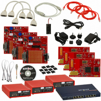
KIT DEV FOR EM250
Manufacturer
Ember
Series
InSightr
Type
802.15.4/Zigbeer
Specifications of EM250-DEV
Frequency
2.4GHz
For Use With/related Products
EM250
Lead Free Status / RoHS Status
Contains lead / RoHS non-compliant
Other names
636-1002


SC1_MODE [0x44AA]
SC1_MODE
0-R
0-R
15
0
0
7
Generation of a 10-bit address is accomplished with two transmit segments. The upper 5 bits of the first
transmit character must be set to
dress. The remaining lower bit contains the command type (“read” or “write”). The second transmit segment
is for the remaining 8 bits of the 10-bit address.
Characters received and transmitted are passed through receive and transmit FIFOs. The SC1 I
transmit and receive FIFOs are 1-byte deep. These FIFOs are accessed under software control.
(Re)start and stop segments are initiated by setting the register bits
SC1_I2CCTRL1
SC_I2CCMDFIN
To initiate a transmit segment, the data have to be written to the
the register bit
tively, the register bit
A receive segment is initiated by setting the register bit
until it clears, and then reading from the
in the
indicates if a NACK or ACK was received from an I
Interrupts are generated on the following events:
To generate interrupts to the CPU, the interrupt masks in the
abled.
5.2.4
0-R
0-R
14
[1:0]
0
0
6
Bus command (
Character transmitted and slave device responded with NACK
Character transmitted (0 to 1 transition of
Character received (0 to 1 transition of
Received and lost character while receive FIFO was full (Receive overrun error)
Transmitted character while transmit FIFO was empty (Transmit underrun error)
SC1_I2CSTAT
Registers
SC1 Mode: 0 = disabled; 1 = UART mode; 2 = SPI mode; 3 = I2C mode. NOTE: To change between
modes, the previous mode must be disabled first.
register followed by waiting until they have cleared. Alternatively, the register bit
in the
SC_I2CSEND
0-R
0-R
13
0
0
5
SC_I2CSTART/SC_I2CSTOP
can be used for waiting. Now the register bit
SC1_I2CSTAT
SC_I2CTXFIN
in the
0x1E
0-R
0-R
12
SC1_I2CCTRL1
0
0
4
can be used for waiting.
in the
. The next 2 bits are for the 2 most significant bits of the 10-bit ad-
SC1_DATA
SC1_I2CSTAT
SC_I2CRXFIN
) completed (0 to 1 transition of
SC_I2CTXFIN
2
C slave device.
register, and completed by waiting until it clears. Alterna-
0-R
0-R
11
0
0
3
data register. Alternatively, the register bit
SC_I2CRECV
)
can be used for waiting.
)
INT_SC1CFG
SC_I2CRXNAK
SC1_DATA
0-R
0-R
10
SC_I2CSTART
0
0
2
in the
and
SC1_I2CCTRL1
data register, followed by setting
INT_CFG
SC_I2CCMDFIN
in the
or
0-RW
0-R
0
9
1
SC_I2CSTOP
SC1_I2CSTAT
registers must be en-
SC1_MODE
120-0082-000I
register, waiting
2
C master
)
SC_I2CRXFIN
EM250
in the
0-RW
0-R
register
0
8
0
47
Related parts for EM250-DEV
Image
Part Number
Description
Manufacturer
Datasheet
Request
R

Part Number:
Description:
IC ZIGBEE SYSTEM-ON-CHIP 48-QFN
Manufacturer:
Ember
Datasheet:

Part Number:
Description:
EM250 RCM BOARD
Manufacturer:
Ember
Datasheet:

Part Number:
Description:
EM250 BREAKOUT BOARD
Manufacturer:
Ember
Datasheet:

Part Number:
Description:
KIT JUMP START FOR EM250
Manufacturer:
Ember
Datasheet:

Part Number:
Description:
KIT EVAL EM250 RF TEST
Manufacturer:
Ember
Datasheet:

Part Number:
Description:
KIT DEV EMBER ZIGBEE W/PCWH
Manufacturer:
Custom Computer Services Inc (CCS)

Part Number:
Description:
PROGRAMMER USB FLASH EM250/260
Manufacturer:
Ember
Datasheet:

Part Number:
Description:
IC ZIGBEE SYSTEM-ON-CHIP 40-QFN
Manufacturer:
Ember
Datasheet:
Part Number:
Description:
IC RF TXRX ZIGBEE 128KB 48QFN
Manufacturer:
Ember
Datasheet:
Part Number:
Description:
IC RF TXRX ZIGBEE 192KB 48QFN
Manufacturer:
Ember
Datasheet:

Part Number:
Description:
INSIGHT ADAPTER FOR EM2XX
Manufacturer:
Ember
Datasheet:

Part Number:
Description:
IAR EWARM LICENCE FOR EM35X
Manufacturer:
Ember
Datasheet:

Part Number:
Description:
INSIGHT ADAPTER 3 FOR EM35X
Manufacturer:
Ember
Datasheet:

Part Number:
Description:
EM35X BREAKOUT BOARD
Manufacturer:
Ember
Datasheet:

Part Number:
Description:
EM260 RCM BOARD
Manufacturer:
Ember
Datasheet: