EM250-DEV Ember, EM250-DEV Datasheet - Page 18
EM250-DEV
Manufacturer Part Number
EM250-DEV
Description
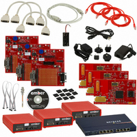
KIT DEV FOR EM250
Manufacturer
Ember
Series
InSightr
Type
802.15.4/Zigbeer
Specifications of EM250-DEV
Frequency
2.4GHz
For Use With/related Products
EM250
Lead Free Status / RoHS Status
Contains lead / RoHS non-compliant
Other names
636-1002


EM250
4.3
4.4
18
Integrated MAC Module
Packet Trace Interface (PTI)
120-0082-000I
4.2.1
The EM250 TX baseband (within the digital domain) performs the spreading of the 4-bit symbol into its IEEE
802.15.4-2003-defined 32-chip I and Q sequence. In addition, it provides the interface for software to perform
the calibration of the TX module in order to reduce process, temperature, and voltage variations.
4.2.2
Even though the EM250 provides an output power suitable for most ZigBee applications, some applications will
require an external power amplifier (PA). Due to the timing requirements of IEEE 802.15.4-2003, the EM250
provides a signal, TX_ACTIVE, to be used for external PA power management and RF Switching logic. When in
TX, the TX Baseband drives TX_ACTIVE high (as described in Table 6). When in RX, the TX_ACTIVE signal is
low. If an external PA is not required, then the TX_ACTIVE signal should be connected to GND through a 100k
Ohm resistor, as shown in the application circuit in Figure 16.
The EM250 integrates critical portions of the IEEE 802.15.4-2003 MAC requirements in hardware. This allows
the microcontroller to provide greater bandwidth to application and network operations. In addition, the
hardware acts as a first-line filter for non-intended packets. The EM250 MAC utilizes a DMA interface to RAM
memory to further reduce the overall microcontroller interaction when transmitting or receiving packets.
When a packet is ready for transmission, the software configures the TX MAC DMA by indicating the packet
buffer RAM location. The MAC waits for the backoff period, then transitions the baseband to TX mode and per-
forms channel assessment. When the channel is clear, the MAC reads data from the RAM buffer, calculates the
CRC, and provides 4-bit symbols to the baseband. When the final byte has been read and sent to the base-
band, the CRC remainder is read and transmitted.
The MAC resides in RX mode most of the time, and different format and address filters keep non-intended
packets from using excessive RAM buffers, as well as preventing the CPU from being interrupted. When the re-
ception of a packet begins, the MAC reads 4-bit symbols from the baseband and calculates the CRC. It assem-
bles the received data for storage in a RAM buffer. A RX MAC DMA provides direct access to the RAM memory.
Once the packet has been received, additional data is appended to the end of the packet in the RAM buffer
space. The appended data provides statistical information on the packet for the software stack.
The primary features of the MAC are:
The EM250 integrates a true PHY-level PTI for effective network-level debugging. This two-signal interface
monitors all the PHY TX and RX packets (in a non-intrusive manner) between the MAC and baseband modules.
It is an asynchronous 500kbps interface and cannot be used to inject packets into the PHY/MAC interface. The
CRC generation, appending, and checking
Hardware timers and interrupts to achieve the MAC symbol timing
Automatic preamble, and SFD pre-pended to a TX packet
Address recognition and packet filtering on received packets
Automatic acknowledgement transmission
Automatic transmission of packets from memory
Automatic transmission after backoff time if channel is clear (CCA)
Automatic acknowledgement checking
Time stamping of received and transmitted messages
Attaching packet information to received packets (LQI, RSSI, gain, time stamp, and packet status)
IEEE 802.15.4 timing and slotted/unslotted timing
TX Baseband
TX_ACTIVE Signal
Related parts for EM250-DEV
Image
Part Number
Description
Manufacturer
Datasheet
Request
R

Part Number:
Description:
IC ZIGBEE SYSTEM-ON-CHIP 48-QFN
Manufacturer:
Ember
Datasheet:

Part Number:
Description:
EM250 RCM BOARD
Manufacturer:
Ember
Datasheet:

Part Number:
Description:
EM250 BREAKOUT BOARD
Manufacturer:
Ember
Datasheet:

Part Number:
Description:
KIT JUMP START FOR EM250
Manufacturer:
Ember
Datasheet:

Part Number:
Description:
KIT EVAL EM250 RF TEST
Manufacturer:
Ember
Datasheet:

Part Number:
Description:
KIT DEV EMBER ZIGBEE W/PCWH
Manufacturer:
Custom Computer Services Inc (CCS)

Part Number:
Description:
PROGRAMMER USB FLASH EM250/260
Manufacturer:
Ember
Datasheet:

Part Number:
Description:
IC ZIGBEE SYSTEM-ON-CHIP 40-QFN
Manufacturer:
Ember
Datasheet:
Part Number:
Description:
IC RF TXRX ZIGBEE 128KB 48QFN
Manufacturer:
Ember
Datasheet:
Part Number:
Description:
IC RF TXRX ZIGBEE 192KB 48QFN
Manufacturer:
Ember
Datasheet:

Part Number:
Description:
INSIGHT ADAPTER FOR EM2XX
Manufacturer:
Ember
Datasheet:

Part Number:
Description:
IAR EWARM LICENCE FOR EM35X
Manufacturer:
Ember
Datasheet:

Part Number:
Description:
INSIGHT ADAPTER 3 FOR EM35X
Manufacturer:
Ember
Datasheet:

Part Number:
Description:
EM35X BREAKOUT BOARD
Manufacturer:
Ember
Datasheet:

Part Number:
Description:
EM260 RCM BOARD
Manufacturer:
Ember
Datasheet: