EM250-DEV Ember, EM250-DEV Datasheet - Page 41
EM250-DEV
Manufacturer Part Number
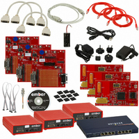
EM250-DEV
Description
KIT DEV FOR EM250
Manufacturer
Ember
Series
InSightr
Type
802.15.4/Zigbeer
Specifications of EM250-DEV
Frequency
2.4GHz
For Use With/related Products
EM250
Lead Free Status / RoHS Status
Contains lead / RoHS non-compliant
Other names
636-1002


Characters transmitted and received are passed through transmit and receive FIFOs. The transmit and receive
FIFOs are 4 bytes deep. The FIFOs are accessed under software control by accessing the
ter or under hardware control by the SC1 DMA.
When a transmit character is written to the (empty) transmit FIFO, the register bit
SC1_UARTSTAT
ters can be written to the transmit FIFO until it is full, which causes the register bit
SC1_UARTSTAT
character becomes available in the transmit FIFO. This causes the register bit
SC1_UARTSTAT
causes the register bit
A received character is stored with its parity and frame error status in the receive FIFO. The register bit
SC1_UARTRXVAL
from the receive FIFO. The error status of a received byte is available with the register bits
and
the receive FIFO to a memory buffer, it checks the stored parity and frame error status flags. When an error is
flagged, the
or frame error.
When the 4-character receive FIFO contains 3 characters, flow control needs to be used to avoid an overflow
event. One method is to use software handshaking by transmitting reserved XON/XOFF characters which are
interpreted by the transmitting terminal to pause further transmissions (to the receive FIFO). Another method
is to use hardware handshaking using XOFF assertion through the nRTS signal.
There are two schemes available to assert the nRTS signal. The first scheme is to initiate nRTS assertion with
software by setting the register bit
sert nRTS automatically depending on the fill state of the receive FIFO. This is enabled with the register bit
SC1_UARTAUTO
The UART also contains overrun protection for both the FIFO and DMA options. If the transmitting terminal
continues to transmit characters to the receive FIFO, only 4 characters are stored in the FIFO. Additional
characters are dropped, and the register bit
receive overrun occur during DMA operation, the
1
1
1
1
1
1
1
SC1_UARTFRMERR
SC1_UARTCFG
0
1
1
1
0
0
-
SC1_RXERRA/B
-
-
0
1
1
0
-
register clears to indicate that not all characters are transmitted yet. Further transmit charac-
register to clear. After shifting one transmit character to the TXD pin, space for one transmit
register to get set. After all characters are shifted out, the transmit FIFO empties, which
in the
in the
-
-
0/1
-
-
-
-
SC1_UARTCFG
in the
SC1_UARTTXIDLE
SC1_UARTSTAT
SC1-2 mode
SC1-2 mode
SC1-4A mode
SC1-4A mode
SC1-4A mode
SC1-4A mode
SC1-3M mode Illegal
register is updated, marking the offset to the first received character with parity
Table 20. Configuration Table for the UART Module
SC1_UARTSTAT
SC1_UARTRTS
register.
register is set to indicate that not all received characters are read out
in the
GPIO Pin Function
TXD/RXD output/input
Illegal
TXD/RXD/nCTS output/input/input
nRTS output = ON/OFF
TXD/RXD/nCTS output/input/input
nRTS output = ON if 2 or more bytes will fit in receive buffer
Reserved
Illegal
SC1_UARTRXOVF
register. When the DMA controller is transferring the data from
SC1_UARTSTAT
SC1_RXERRA/B
in the
SC1_UARTCFG
in the
register to get set.
registers mark the error-offset. The RX FIFO
SC1_UARTSTAT
register. The second scheme is to as-
SC1_UARTTXFREE
SC1_UARTTXIDLE
register is set. Should this
SC1_UARTTXFREE
SC1_DATA
120-0082-000I
SC1_UARTPARERR
in the
EM250
data regis-
in the
in the
41
Related parts for EM250-DEV
Image
Part Number
Description
Manufacturer
Datasheet
Request
R

Part Number:
Description:
IC ZIGBEE SYSTEM-ON-CHIP 48-QFN
Manufacturer:
Ember
Datasheet:

Part Number:
Description:
EM250 RCM BOARD
Manufacturer:
Ember
Datasheet:

Part Number:
Description:
EM250 BREAKOUT BOARD
Manufacturer:
Ember
Datasheet:

Part Number:
Description:
KIT JUMP START FOR EM250
Manufacturer:
Ember
Datasheet:

Part Number:
Description:
KIT EVAL EM250 RF TEST
Manufacturer:
Ember
Datasheet:

Part Number:
Description:
KIT DEV EMBER ZIGBEE W/PCWH
Manufacturer:
Custom Computer Services Inc (CCS)

Part Number:
Description:
PROGRAMMER USB FLASH EM250/260
Manufacturer:
Ember
Datasheet:

Part Number:
Description:
IC ZIGBEE SYSTEM-ON-CHIP 40-QFN
Manufacturer:
Ember
Datasheet:
Part Number:
Description:
IC RF TXRX ZIGBEE 128KB 48QFN
Manufacturer:
Ember
Datasheet:
Part Number:
Description:
IC RF TXRX ZIGBEE 192KB 48QFN
Manufacturer:
Ember
Datasheet:

Part Number:
Description:
INSIGHT ADAPTER FOR EM2XX
Manufacturer:
Ember
Datasheet:

Part Number:
Description:
IAR EWARM LICENCE FOR EM35X
Manufacturer:
Ember
Datasheet:

Part Number:
Description:
INSIGHT ADAPTER 3 FOR EM35X
Manufacturer:
Ember
Datasheet:

Part Number:
Description:
EM35X BREAKOUT BOARD
Manufacturer:
Ember
Datasheet:

Part Number:
Description:
EM260 RCM BOARD
Manufacturer:
Ember
Datasheet: