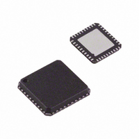
AD8339ACPZ Analog Devices Inc, AD8339ACPZ Datasheet - Page 3

AD8339ACPZ
Manufacturer Part Number
AD8339ACPZ
Description
IC I/Q DEMOD QUAD 50MHZ 40-LFCSP
Manufacturer
Analog Devices Inc
Datasheet
1.AD8339ACPZ.pdf
(36 pages)
Specifications of AD8339ACPZ
Function
Demodulator
Lo Frequency
0Hz ~ 200MHz
Rf Frequency
0Hz ~ 50MHz
P1db
14.8dBm
Gain
-1.3dB
Noise Figure
11.5dB
Current - Supply
35mA
Voltage - Supply
4.5 V ~ 5.5 V
Package / Case
40-VFQFN, 40-CSP, Exposed Pad
Frequency Range
DC To 50MHz
Rf Type
Quadrature
Supply Voltage Range
± 4.5V To ± 5.5V
Rf Ic Case Style
LFCSP
No. Of Pins
40
Operating Temperature Range
-40°C To +85°C
Lead Free Status / RoHS Status
Lead free / RoHS Compliant
For Use With
AD8339-EVALZ - BOARD EVAL AD8339 I/Q DEMOD
Lead Free Status / RoHS Status
Lead free / RoHS Compliant, Lead free / RoHS Compliant
Available stocks
Company
Part Number
Manufacturer
Quantity
Price
Company:
Part Number:
AD8339ACPZ
Manufacturer:
Analog Devices Inc
Quantity:
135
SPECIFICATIONS
V
noted. Single-channel AD8021 LPF values: R
Table 1.
Parameter
OPERATING CONDITIONS
DEMODULATOR PERFORMANCE
PHASE ROTATION PERFORMANCE
S
Local Oscillator (LO) Frequency
RF Frequency Range
Baseband Bandwidth
LO Input Level
Supply Voltage (V
Temperature Range
Input Impedance
Transconductance
Dynamic Range
Maximum Input Swing
Peak Output Current (No Filtering)
Input P1dB
Third-Order Intermodulation (IM3)
Third-Order Input Intercept (IIP3)
LO Leakage
Conversion Gain
Input Referred Noise
Output Current Noise
Noise Figure
Bias Current
LO Common-Mode Range
RF Common-Mode Voltage
Output Compliance Range
Phase Increment
Quadrature Phase Error
I/Q Amplitude Imbalance
Channel-to-Channel Matching
= ±5 V, T
Range
Equal Input Levels
Unequal Input Levels
A
= 25°C, 4f
S
)
LO
= 20 MHz, f
RF
= 5.01 MHz, f
Test Conditions/Comments
4× internal LO at Pin 4LOP and Pin 4LON, square wave
drive via LVDS (see Figure 64)
Mixing
Limited by external filtering
RF, differential
LO, differential
Demodulated I
filtering measured from RF inputs, all phases
IP1dB − input referred noise (dBm)
Differential; inputs biased at 2.5 V; Pin RFxP, Pin RFxN
0° phase shift
45° phase shift
Ref = 50 Ω
Ref = 1 V rms
f
Baseband tones: 0 dBm @ 8 kHz and 13 kHz
Baseband tones: −1 dBm @ 8 kHz and −31 dBm @ 13 kHz
f
Measured at RF inputs, worst phase, measured into 50 Ω
Measured at baseband outputs, worst phase, AD8021
disabled, measured into 50 Ω
All codes, see Figure 42
Output noise/conversion gain (see Figure 47)
Output noise/R
With AD8334 LNA
R
R
R
Pin 4LOP and Pin 4LON
Pin RFxP and Pin RFxN
Pin 4LOP and Pin 4LON (each pin)
For maximum differential swing; Pin RFxP and Pin RFxN
(dc-coupled to AD8334 LNA output)
Pin IxOP and Pin QxOP
One channel is reference; others are stepped
16 phase steps per channel
Ix to Qx; all phases, 1σ
Ix to Qx; all phases, 1σ
Phase match I-to-I and Q-to-Q; −40°C < T
Amplitude match I-to-I and Q-to-Q; −40°C < T
RF1
RF1
S
S
S
= 50 Ω, R
= 50 Ω, R
= 50 Ω, R
FILT
= 5.010 MHz, f
= 5.010 MHz, f
= 787 Ω and C
FB
FB
FB
BB
= ∞
= 1.1 kΩ
= 274 Ω
OUT
= 10 kHz, P
FILT
/V
RF2
RF2
IN
Rev. A | Page 3 of 36
= 5.015 MHz, f
= 5.015 MHz, f
; each Ix or Qx output after low-pass
FILT
= 2.2 nF (see Figure 53).
LO
≥ 0 dBm, per channel performance, dBm (50 Ω), unless otherwise
LO
LO
= 5.023 MHz
= 5.023 MHz
A
< +85°C
A
< +85°C
Min
0.01
DC
DC
±4.5
−40
0.2
−1.5
−2
Typ
0
±5.0
25||10
100||4
1.15
160
2.8
±2.4
±3.1
14.8
1.85
−60
−66
31
−118
−68
−1.3
11.8
12.9
8.4
9.1
11.5
−3
−45
2.5
22.5
±1
±0.05
±1
±0.1
Max
200
50
50
13
±5.5
+85
3.8
+0.7
+2
AD8339
Unit
MHz
MHz
MHz
dBm
V
°C
kΩ||pF
kΩ||pF
mS
dB/Hz
V p-p
mA
mA
dBm
dBV
dBc
dBc
dBm
dBm
dBm
dB
nV/√Hz
pA/√Hz
dB
dB
dB
μA
μA
V
V
V
Degrees
Degrees
dB
Degrees
dB


