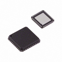
AD8339ACPZ Analog Devices Inc, AD8339ACPZ Datasheet - Page 29

AD8339ACPZ
Manufacturer Part Number
AD8339ACPZ
Description
IC I/Q DEMOD QUAD 50MHZ 40-LFCSP
Manufacturer
Analog Devices Inc
Datasheet
1.AD8339ACPZ.pdf
(36 pages)
Specifications of AD8339ACPZ
Function
Demodulator
Lo Frequency
0Hz ~ 200MHz
Rf Frequency
0Hz ~ 50MHz
P1db
14.8dBm
Gain
-1.3dB
Noise Figure
11.5dB
Current - Supply
35mA
Voltage - Supply
4.5 V ~ 5.5 V
Package / Case
40-VFQFN, 40-CSP, Exposed Pad
Frequency Range
DC To 50MHz
Rf Type
Quadrature
Supply Voltage Range
± 4.5V To ± 5.5V
Rf Ic Case Style
LFCSP
No. Of Pins
40
Operating Temperature Range
-40°C To +85°C
Lead Free Status / RoHS Status
Lead free / RoHS Compliant
For Use With
AD8339-EVALZ - BOARD EVAL AD8339 I/Q DEMOD
Lead Free Status / RoHS Status
Lead free / RoHS Compliant, Lead free / RoHS Compliant
Available stocks
Company
Part Number
Manufacturer
Quantity
Price
Company:
Part Number:
AD8339ACPZ
Manufacturer:
Analog Devices Inc
Quantity:
135
Using the SPI Port
Channel and phase selection are accessed via the SPI port on
the AD8339, and the evaluation board provides two means of
access. If it is desired to exercise the SPI input with custom
waveforms, the SDI, SCLK, and CSB pins are available at the
auxiliary connector P1. A digital pattern generator can be
programmed in conformance with the timing diagram shown
in Figure 57.
The most convenient way to select channels and phase delays
is through the USB port of a PC using the executable program
provided on the CD or at the Analog Devices, Inc., website.
Copy the .EXE and .MSI files into the same folder on the PC.
Double-click the .EXE file to install the program and place a
shortcut on the desktop. Double-clicking the desktop icon
opens the control menu, as shown in Figure 62.
Table 7. Jumper and Header List
Jumper, Header
CSB
CSBG
EN12, EN34
I1234
Q1234
RF1 to RF4
RSTS
RSET
SCLK
SDI
SLKG
4LO
Description
Connects the chip select input to the connector or the USB inputs—normally connected to USB (test)
Grounds the CSB input—shipped omitted
Enables or disables Channel 1 through Channel 4—boards shipped enabled
Sums all four I-channel current outputs together—shipped omitted
Sums all four Q-channel current outputs together—shipped omitted
Test points for the LNA outputs—a differential probe fits these
Resets the SPI input—shipped omitted
Resets the local oscillator input—shipped omitted
Connects the serial clock input to the connector or to the USB inputs—normally connected to USB (test)
Connects the serial data input to the connector or to the USB input—normally connected to USB (test)
Grounds the serial clock input—shipped omitted
Test pins for the 4LO level shifter output—a differential probe fits these
Figure 62. SPI Software Control Menu
Rev. A | Page 29 of 36
The menu consists of an array of options that are self-explanatory.
Channels are enabled or disabled by selecting the channels in
the Channel Enable list, and the 16 phase options are selected
from the list box for each of the channels.
Hardwired Jumpers
Hardwired jumpers provide for interconnection of channels
and as a means for measuring output voltages at various
strategic nodes (see Table 7).
As shipped, the evaluation board is configured to connect all
the AD8339 RF inputs to a single LNA output. In this configur-
ation, the phases of the four channels can be shifted throughout
the full range and the outputs can be viewed on a multichannel
scope using one of the channels as a reference. To operate all the
LNA channels independently, it is only necessary to move the
input shorting jumpers to the channel RF outputs.
AD8339


