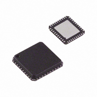
AD8339ACPZ Analog Devices Inc, AD8339ACPZ Datasheet - Page 20

AD8339ACPZ
Manufacturer Part Number
AD8339ACPZ
Description
IC I/Q DEMOD QUAD 50MHZ 40-LFCSP
Manufacturer
Analog Devices Inc
Datasheet
1.AD8339ACPZ.pdf
(36 pages)
Specifications of AD8339ACPZ
Function
Demodulator
Lo Frequency
0Hz ~ 200MHz
Rf Frequency
0Hz ~ 50MHz
P1db
14.8dBm
Gain
-1.3dB
Noise Figure
11.5dB
Current - Supply
35mA
Voltage - Supply
4.5 V ~ 5.5 V
Package / Case
40-VFQFN, 40-CSP, Exposed Pad
Frequency Range
DC To 50MHz
Rf Type
Quadrature
Supply Voltage Range
± 4.5V To ± 5.5V
Rf Ic Case Style
LFCSP
No. Of Pins
40
Operating Temperature Range
-40°C To +85°C
Lead Free Status / RoHS Status
Lead free / RoHS Compliant
For Use With
AD8339-EVALZ - BOARD EVAL AD8339 I/Q DEMOD
Lead Free Status / RoHS Status
Lead free / RoHS Compliant, Lead free / RoHS Compliant
Available stocks
Company
Part Number
Manufacturer
Quantity
Price
Company:
Part Number:
AD8339ACPZ
Manufacturer:
Analog Devices Inc
Quantity:
135
AD8339
To determine the input referred noise, it is important to know
the active low-pass filter (LPF) values R
Figure 53. Typical filter values for a single channel are 1.58 kΩ
for R
single-pole LPF. If two channels are summed, as is done on the
AD8339 evaluation board, the resistor value is halved (787 Ω)
and the capacitor value is doubled (2.2 nF), maintaining the
same pole frequency at twice the AD8339 current.
If the RF and LO are offset by 10 kHz, the demodulated signal is
10 kHz and is passed by the LPF. The single-channel mixing gain
from the RF input to the
is approximately 1.7× (4.7 dB) for 1.58 kΩ and 1 nF, or 6 dB less
for filter values of 787 Ω and 2.2 nF (0.85× or −1.3 dB). The
noise contributed by the AD8339 is then 11 nV/√Hz × 1.7 or
~18.7 nV/√Hz at the AD8021 output. The combined noise of
the AD8021 and the 1.58 kΩ feedback resistor is 6.3 nV/√Hz, so
the total output referred noise is approximately 19.7 nV/√Hz.
This value can be adjusted by increasing the filter resistor while
FILT
TRANSMITTER
TRANSDUCER
and 1 nF for C
T/R
SW
T/R
SW
T/R
SW
T/R
SW
FILT
AD8332, AD8334 LNA
AD8021
OR AD8335 PREAMP
; these values implement a 100 kHz
R
R
R
R
FB
FB
FB
FB
output (for example, I1´, Q1´)
FILT
and C
2
2
2
2
Figure 53. Interconnection Block Diagram for the AD8339
AD8339
FILT
QUADRATURE
, shown in
DIVIDER
0° 90°
CLOCK
SYSTEM TIMING
2
2
2
2
2
2
2
2
Rev. A | Page 20 of 36
CONTROLLER
2
2
2
2
2
2
2
2
SDI
maintaining the corner frequency, thereby increasing the gain.
The factor limiting the magnitude of the gain is the output
swing and drive capability of the op amp selected for the I-to-V
converter, in this example, the AD8021.
The limitation on the number of channels summed is the drive
capability of the amplifier, as explained in detail in the Channel
Summing section.
MULTICHANNEL SUMMATION
Analog Beamforming
Beamforming, as applied to medical ultrasound, is defined as
the phase alignment and summation of signals generated from a
common source, but received at different times by a multielement
ultrasound transducer. Beamforming has two functions: it imparts
directivity to the transducer, enhancing its gain, and it defines a
focal point within the body from which the location of the
returning echo is derived. The primary application for the
AD8339 is in analog beamforming circuits for ultrasound.
Φ
Φ
Φ
Φ
Φ
Φ
Φ
Φ
DATA
I1
Q1
I2
Q2
I3
Q3
I4
Q4
C
R
C
R
FILT
FILT
FILT
FILT
AD8021
AD8021
ΣI
ΣQ
16-BIT ADC
16-BIT ADC
AD7665 OR
AD7665 OR
AD7686
AD7686
I DATA
Q DATA


