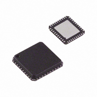
AD8339ACPZ Analog Devices Inc, AD8339ACPZ Datasheet - Page 18

AD8339ACPZ
Manufacturer Part Number
AD8339ACPZ
Description
IC I/Q DEMOD QUAD 50MHZ 40-LFCSP
Manufacturer
Analog Devices Inc
Datasheet
1.AD8339ACPZ.pdf
(36 pages)
Specifications of AD8339ACPZ
Function
Demodulator
Lo Frequency
0Hz ~ 200MHz
Rf Frequency
0Hz ~ 50MHz
P1db
14.8dBm
Gain
-1.3dB
Noise Figure
11.5dB
Current - Supply
35mA
Voltage - Supply
4.5 V ~ 5.5 V
Package / Case
40-VFQFN, 40-CSP, Exposed Pad
Frequency Range
DC To 50MHz
Rf Type
Quadrature
Supply Voltage Range
± 4.5V To ± 5.5V
Rf Ic Case Style
LFCSP
No. Of Pins
40
Operating Temperature Range
-40°C To +85°C
Lead Free Status / RoHS Status
Lead free / RoHS Compliant
For Use With
AD8339-EVALZ - BOARD EVAL AD8339 I/Q DEMOD
Lead Free Status / RoHS Status
Lead free / RoHS Compliant, Lead free / RoHS Compliant
Available stocks
Company
Part Number
Manufacturer
Quantity
Price
Company:
Part Number:
AD8339ACPZ
Manufacturer:
Analog Devices Inc
Quantity:
135
AD8339
THEORY OF OPERATION
The AD8339 is a quad I/Q demodulator with a programmable
phase shifter for each channel. The primary application is
phased array beamforming in medical ultrasound. Other
potential applications include phased array radar and smart
antennas for mobile communications. The AD8339 can also be
used in applications that require multiple well-matched I/Q
demodulators. The AD8339 is architecturally very similar to its
predecessor, the AD8333. The major differences are
•
•
Figure 52 shows the block diagram and pinout of the AD8339.
The analog inputs include the four RF inputs, which accept signals
from the RF sources, and a local oscillator (applied to differential
input pins marked 4LOP and 4LON) common to all channels.
The addition of a serial (SPI) interface that allows daisy
chaining of multiple devices
Reduced power per channel
COMM
COMM
SCLK
VPOS
VPOS
RF2N
RF2P
RF3P
RF3N
CSB
10
1
2
3
4
5
6
7
8
9
AD8339
BIAS
INTERFACE
RSTS
VPOS
SERIAL
40
11
(SPI)
SDO
SDI
39
12
RF1P
RF4P
38
13
Figure 52. AD8339 Block Diagram
RF1N
RF4N
37
14
Rev. A | Page 18 of 36
COMM
COMM
90°
0°
36
15
V TO I
V TO I
V TO I
V TO I
LOCAL OSCILLATOR DIVIDE BY 4
VPOS
VPOS
35
16
0°
Each channel can be shifted up to 347.5° in 16 increments, or
22.5° per increment, via the SPI port. The AD8339 has two reset
inputs: RSET synchronizes the LO dividers when multiple
AD8339s are used in arrays; RSTS sets all the SPI port control
bits to 0. RSTS is used for testing or to disable the AD8339
without the need to program it via the SPI port.
The I and Q outputs are current-formatted and summed together
for beamforming applications. A transimpedance amplifier
using an AD8021 op amp is a nearly ideal method for summing
multiple channels and current-to-voltage conversion because
each of the AD8339 outputs is terminated by a virtual ground.
A further advantage of the transimpedance amplifier is the
simple implementation of high-pass filtering and the flexible
number of channels accommodated.
LODC
RSET
34
17
Φ
Φ
Φ
Φ
Φ
Φ
Φ
Φ
I1OP
I4OP
33
18
CURRENT
CURRENT
CURRENT
CURRENT
CURRENT
CURRENT
CURRENT
CURRENT
MIRROR
MIRROR
MIRROR
MIRROR
MIRROR
MIRROR
MIRROR
MIRROR
Q1OP
Q4OP
32
19
VNEG
VNEG
31
20
30
29
28
27
26
25
24
23
22
21
Q2OP
I2OP
VPOS
VPOS
4LOP
4LON
VNEG
VNEG
I3OP
Q3OP


